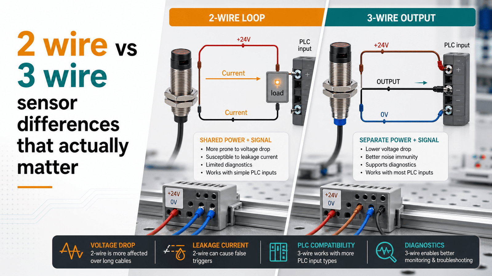
The main difference in a 2 wire vs 3 wire sensor is wiring: a 2-wire sensor shares power and signal on the same two wires (connected in series with the load), while a 3-wire sensor uses separate wires for power (DC+, DC−) and output. This affects performance—2-wire sensors leak 0.5–2.5 mA residual current when “off,” whereas 3-wire types cause near-zero voltage drop, switch faster, and come in NPN (sinking) or PNP (sourcing) configurations for PLC inputs.
How does each one get wired up? And why does a 2-wire sensor leak a little current even when it is switched off?
Which of the two handles fast switching better? What do NPN and PNP actually mean when you are dealing with a 3-wire sensor? And which one should you pick for your PLC input in the end?
Quick Takeaways
- Wire 2-wire sensors in series with the load using two conductors.
- Wire 3-wire sensors with separate DC+, DC−, and switched output lines.
- Choose 3-wire sensors for fast switching and high-speed PLC counting inputs.
- Avoid 2-wire sensors on low-current PLC inputs due to residual leakage.
- Match PNP (sourcing) or NPN (sinking) output to your PLC card.
What’s the difference between a 2 wire and 3 wire sensor?
A 2-wire sensor pushes both the power and the output signal through the very same pair of wires, and those wires get connected in series with the load. A 3-wire sensor, on the other hand, spreads that same work across three separate lines, which are DC+, DC− (the common line), and a dedicated switched output all its own. This one difference in the wiring actually changes the leakage current, the voltage drop, and how cleanly the device talks to a PLC input card, going by industrial DC sensor references (2025).
What this means out on the plant floor is that a 2-wire device never quite switches OFF completely. Since the loop has to stay powered up to run the sensor’s own internal electronics, a small leakage current of roughly 0.5 to 2 mA is always flowing through it, which is enough to hold a low-current PLC input stuck in a false-ON state. A 3-wire sensor gets around this problem entirely, because its output line is dedicated, so the OFF state reads clean and sits near zero.
Here is the core 2 wire vs 3 wire sensor comparison, all laid out at a glance:
| Attribute | 2-wire sensor | 3-wire sensor |
|---|---|---|
| Wiring | Series with load, shared loop | Separate power + signal line |
| OFF-state leakage | Higher (0.5–2 mA typical) | Very low (under 0.1 mA) |
| Voltage drop when ON | Higher across the sensor | Minimal, output is switched |
| PLC compatibility | Risk of false-ON on low-current inputs | Clean high/low, broad card support |
| Install complexity | Simpler, fewer terminals | One extra conductor |
Go with a 2-wire when the terminals are tight and the input load pulls a steady current. Reach for a 3-wire when you need high reliability, or when the environment is electrically noisy. Considering all of that, the next sections break down series wiring, the leakage math, and how NPN and PNP outputs match up with your card.
How does a 2 wire sensor work in series with the load?
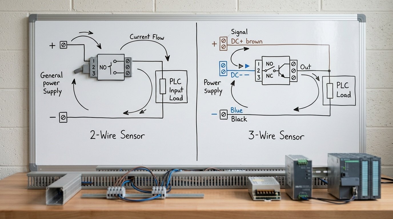
A 2-wire sensor sits directly in the current path with the load, so the same current that powers the sensor also drives the load. Because the sensor’s internal electronics never fully stop drawing current, a small residual current always flows even in the OFF state. In the 2025 series-loop model, power and signal share one two-wire path.
Picture a single loop: supply positive, through the sensor, through the load, back to supply negative. When the sensor switches ON, it acts like a closed switch and lets full current pass. When OFF, it acts like a slightly leaky switch, and that leakage keeps the internal circuit alive.
This design is common in inductive proximity switches and capacitive level probes, where wiring space is tight. It saves one conductor per device, a real cost win across hundreds of I/O points.
Why do polarity and minimum operating current matter?
Get the polarity backward and a DC 2-wire sensor simply won’t switch, the internal diode blocks reverse flow. That’s a key gap in the 2 wire vs 3 wire sensor comparison, since many 3-wire types tolerate miswiring better. Two specs govern reliable operation:
- Burden voltage: the volts dropped across the ON sensor (often 3–8 V[1]), which the load never sees.
- Minimum operating current: the load must draw enough current (commonly 3–5 mA) for the sensor to stay powered and reliable.
Undersize the load current and the sensor chatters or fails to hold ON.

How does a 3 wire sensor separate power and signal and why does that matter?
A 3-wire sensor uses two of its wires to carry power, which are the DC positive and DC negative lines, while the third wire is set aside purely for the output signal, according to Rockwell-style PLC wiring guidance from 2024. Because power and signal are kept apart this way, the electronics inside the sensor always receive the full supply voltage they need. That lets the switched output turn on and off cleanly without ever having to send current through the load. In the 2-wire design, power and signal are forced to share a single loop, but the 3-wire design gives each of those jobs its own separate path to work in.
What do the three lines actually do?
- V+ (DC positive): this line supplies the sensor with 10 to 30 VDC at all times, so the circuit that does the detecting never runs short on power.
- Common (DC−): this is the shared ground return, and keeping it separate from the signal ground helps the sensor shrug off electrical noise, according to 2024 industrial automation commentary.
- Output signal: this is a separate switched line, either NPN or PNP, and it carries nothing but the ON or OFF state back to the PLC input.
Why does this make signal integrity higher?
Since the output stage is running on a steady rail voltage, it produces sharp switching edges and keeps its OFF-state leakage below 0.1 mA. That is far lower than the 0.5 to 2 mA you get from a 2-wire device that is wired in series. A clean transition like that is exactly what a PLC digital input is looking for when it needs to read a solid logic 1 or a solid logic 0. This is really the reason 3-wire sensors are so common on modern PLC discrete inputs, because they respond faster, cause fewer false triggers, and behave in a predictable way across a wide range of loads.
Anyone weighing the 2 wire vs 3 wire sensor choice usually lands here for that dependability.
Why does leakage current in 2 wire sensors cause PLC false-ON states?
A 2-wire sensor never truly stops the flow of current. Even when it’s switched OFF, it leaks somewhere around 0.5 to 2 mA just to keep its internal electronics powered and alive. If that leftover current happens to go above the OFF-state threshold on your PLC input card, the input locks onto a false ON, which means the PLC “sees” a signal that really isn’t there at all. This is the single most common thing that goes wrong when you look at a 2 wire vs 3 wire sensor comparison, and 2-wire proximity sensors are documented to show higher OFF-state leakage than 3-wire types.
How do you read the input card’s leakage spec sheet?
You’ll want to find two numbers on the PLC datasheet: the OFF-state current (max) and the OFF-state voltage threshold. A typical 24 VDC discrete input generally treats anything below roughly 5 VDC, or under 1.5 mA, as being OFF. The card’s “max leakage to guarantee OFF” is what tells you the ceiling you’re working with.
And here is where the trap sits: if your sensor leaks 2 mA but the card only guarantees OFF below 1.5 mA, the input floats high and misfires on you. High-impedance input cards actually make this worse, because even a small current builds up a large voltage across them.
How do you calculate whether a sensor will misfire?
You basically multiply the sensor leakage by the input’s impedance. Say the card has 3 kΩ of input resistance and the sensor leaks 2 mA: 0.002 A × 3000 Ω = 6 V. That 6 V sits above the 5 V[2] OFF threshold, so the input just stays ON. Compare the result against the card’s guaranteed-OFF voltage before you go and wire anything up. And if it fails that check, you fix it with a bleeder resistor, which is covered next.

How do you size a bleeder resistor to fix 2 wire sensor leakage?
Pick a bleeder resistor that pulls the sensor’s OFF-state leakage current safely below the PLC input’s false-ON threshold. Since 2-wire proximity sensors carry higher leakage current in the OFF state than 3-wire types, per 2025 sensor engineering data, a resistor wired in parallel with the input diverts that stray current so the residual voltage drops below the trigger point. It gives leakage a low-resistance path, so most of the current flows through the resistor instead of building voltage at the input terminal.
⚠️ Common mistake: Using a 2-wire sensor on a low-current PLC input, causing phantom “on” signals even when the sensor is off. This happens because 2-wire sensors leak 0.5–2.5 mA residual current to stay powered, which can exceed the PLC input’s off-threshold and register false triggers. The fix: use a 3-wire sensor (near-zero leakage, matched NPN/PNP) for low-current or high-speed counting inputs.
Say your sensor leaks 1.7 mA in the OFF state. The PLC needs the OFF voltage under 5 V on a 24 V circuit. To pull that residual below 5 V, size the resistor from Ohm’s law:
- Target: R = V ÷ I = 5 V[3] ÷ 0.0017 A ≈ 2,940 Ω, so pick a standard 2.7 kΩ.
- Power rating: P = V² ÷ R = 24² ÷ 2700 ≈ 0.21 W when the sensor is ON, so use a 1 W resistor for margin.
The trade-off is real: that resistor burns heat continuously, adds a wiring point, and if it opens, the false-ON returns. This is exactly why the 2 wire vs 3 wire sensor choice matters, a 3-wire device skips the resistor entirely.
How do you match 2 wire and 3 wire sensors to sinking NPN vs sourcing PNP PLC cards?
Match by output type: an NPN (sinking) 3-wire sensor needs a sourcing input card, and a PNP (sourcing) 3-wire sensor needs a sinking input card. A 2-wire sensor has no NPN/PNP output at all, so it works with either card type, you only have to get the polarity right. In the 2 wire vs 3 wire sensor decision, this pairing rule prevents inputs that never turn on.
Sinking means the switched wire pulls the input Down to ground. Sourcing means it pushes Voltage out to the input. An NPN output switches to the negative rail, so the PLC input must supply the positive side, that’s a sourcing card. Flip it for PNP.
How do you wire a 3-wire NPN or PNP sensor to a PLC?
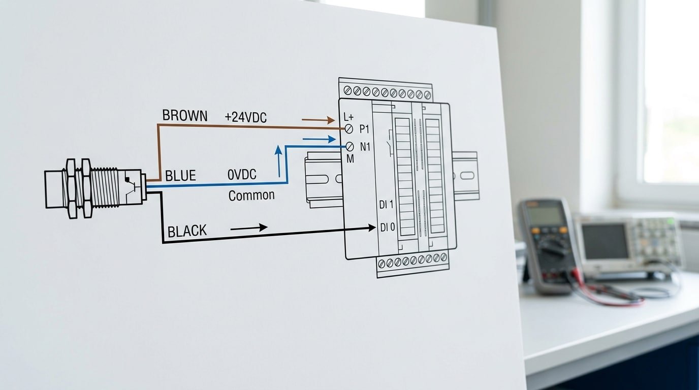
- NPN sensor → sourcing card: brown to +24V[4], blue to 0V, black (output) to the PLC input terminal.
- PNP sensor → sinking card: brown to +24V, blue to 0V, black to the input; card common ties to 0V[5].
Industry data from 2025 shows PNP dominates European and North American panels, so most modern DC input cards ship as sinking by default.
Why is a 2-wire sensor card-agnostic but polarity-sensitive?
A 2-wire sensor carries power and signal on one loop, so it has no dedicated output transistor to define sinking or sourcing. Reverse the two wires on a DC unit, though, and it won’t conduct or may fail. Confirm brown-positive, blue-negative before power-up.
When does voltage drop make a 2 wire sensor unsuitable?
A 2-wire sensor becomes unsuitable when its burden voltage plus cable resistance drop leaves the load with too little voltage to operate. On a 12 V DC loop, a sensor with a 6 V burden voltage already eats half your supply before cable losses even start. Switch to a 3-wire sensor once your remaining voltage margin drops below the load’s minimum turn-on level.
Burden voltage is the voltage the 2-wire sensor keeps for itself just to stay powered, commonly 5,8 V in the ON state, all of it gone before the load ever sees it. A 3-wire sensor instead powers itself from the full supply and switches nearly the entire rail to the load.
How much does cable resistance add on a long run?
Copper resistance stacks up fast on thin, long cables. A 100 m run of 0.5 mm[6]² wire has roughly 3.5 Ω per conductor, so 7 Ω round-trip.
At 200 mA load current, that costs 1.4 V by Ohm’s law (V = I × R). See the AWG resistance tables for exact figures per gauge.
| Scenario | Burden V | Cable drop | Left for load (24 V) | Verdict |
|---|---|---|---|---|
| Short run, 24 V[7] | 6 V | 0.3 V | 17.7 V | 2-wire OK |
| 100 m run, 24 V[8] | 6 V | 1.4 V | 16.6 V[9] | 2-wire marginal |
| 100 m run, 12 V | 6 V | 1.4 V | 4.6 V[10] | Use 3-wire |
The rule in the 2 wire vs 3 wire sensor decision: if load-side voltage falls under the load’s rated minimum with a 15% safety cushion, go 3-wire.
Should you choose a 2 wire or 3 wire sensor? A decision flowchart
Default to a 3-wire sensor for DC discrete inputs. Choose a 2-wire sensor only when terminals are scarce and the load current safely clears the PLC input’s ON/OFF thresholds. Since 2-wire types leak more OFF-state current than 3-wire types, per Macher Sensor’s 2025 comparison, low-current inputs push you toward 3-wire every time.
Run through these paths before you order:
| Your situation | Pick this | Why |
|---|---|---|
| Long cable run + 24 V DC supply | 3-wire | 2-wire burden voltage plus line drop starves the load |
| Terminal count is tight (retrofit) | 2-wire | No separate output wire needed |
| PLC input has low leakage tolerance (under 1.5 mA) | 3-wire | 2-wire residual current risks false-ON |
| Driving a small relay or LED load | 3-wire | Reset current too low for 2-wire leakage |
| Simple lamp or high-current contactor | 2-wire | High load current masks leakage |
Chasing a false-ON that won’t clear? Check the input’s stated OFF threshold. If your 2-wire sensor’s leakage sits within approximately 30% of that number, don’t add another bleeder resistor and hope. Swap to a 3-wire PNP or NPN device and the problem disappears at the source.
One field rule saves rework: when you can’t confirm the PLC card’s leakage rating, spec 3-wire. It costs a few cents more per unit but avoids the intermittent faults that eat initial startup hours.
Frequently asked questions about 2 wire vs 3 wire sensors
The most common 2 wire vs 3 wire sensor questions come down to conversion, load resistors, analog signals, and false-ON readings. Short answer: you can’t cleanly convert one to the other because they use different circuit topologies, and a 2-wire sensor reading “on” with no target present usually means leakage current, not a broken sensor.
Can you convert a 2-wire sensor to 3-wire?
No. The two designs are built differently at the circuit level. A 2-wire device shares power and signal on one loop, while a 3-wire device has a dedicated output transistor and separate supply lines. You can’t rewire one into the other. Just buy the sensor type your input card needs.
Do 2-wire sensors need a load resistor?
Sometimes. When a 2-wire sensor drives a high-impedance PLC input, its OFF-state leakage can hold the input above the logic-low threshold. Adding a bleeder resistor in parallel with the input gives that leakage a path to ground, dropping the residual voltage below the false-ON level.
Which is better for analog signals?
For 4,20 mA transmitters, 2-wire loop-powered designs cut wiring effort and improve EMC (how well a device resists electrical interference), since noise is easier to filter in a current loop, per WIKA (2024). Choose 3-wire only when you need higher ohmic load capacity.
Why does a 2-wire sensor read on with no target?
Residual voltage. A 2-wire sensor never stops current fully, so its 0.5,2 mA OFF-state leakage can trip a sensitive input. Fix it with a bleeder resistor or switch to 3-wire.
Choosing the right sensor wiring for reliable inputs
Pick your sensor wiring by three numbers: OFF-state leakage, burden voltage drop, and output type match. A 3-wire sensor wins for DC discrete PLC inputs because it keeps leakage low and clean switching high. Reserve the 2-wire sensor for jobs where saving a conductor matters more than tight electrical margins.
Of those three numbers, leakage current is the deciding factor for discrete PLC inputs. A 2-wire proximity sensor leaks 0.5,2 mA of measurable OFF-state current and shows residual voltage, which can falsely trigger a PLC input when the load’s reset current is low. Three-wire devices keep both under 0.1 mA, so they behave cleanly on modern high-impedance input cards, per sensor manufacturer specifications (2025).
When does each wiring type actually win?
Choose 3-wire for DC discrete inputs, high-speed switching, and any card with a high input impedance. Choose 2-wire when you must save a conductor in a crowded conduit, or for analog 4,20 mA loops where the shared current path improves EMC and cuts wiring errors, according to WIKA transmitter guidance (2024).
What should you verify before you order?
Check your PLC input card’s datasheet for two values. First, the maximum OFF-state (leakage) current the input tolerates before reading false-ON. Second, the input burden and minimum ON voltage. Match sinking (NPN) sensors to sourcing inputs and sourcing (PNP) sensors to sinking inputs. Confirm the sensor’s residual voltage sits below your card’s ON threshold. Order only after both numbers clear.
See also
PNP sensor wiring diagram with simple step by step guide
NPN vs PNP sensor outputs explained for PLC wiring
Which analog proximity sensor output is better, 0–10 V or 4–20 mA
Normally open vs normally closed sensor basics and use cases




