
Sensor Replacement Guide: How to Check Compatibility Before You Buy
A suitable sensor replacement must match the machine’s function, electrical interface, physical installation and real-target detection—not just its voltage or shape. Start with the exact old model and accepted settings, resolve any differences in the proposed part, then verify the result in a controlled machine test.
Do you need a new sensor—or is the fault elsewhere?
Replace the sensor only after separating a sensing problem from a wiring, mounting or control problem. A loose bracket, damaged cable or missed PLC pulse can remain after a new sensor is installed.
- No power indication: check the documented supply circuit, connector and cable before condemning the sensor. An unlit indicator alone does not identify the failed component.
- The sensor indicates detection, but the machine does not respond: trace the output to the input module and PLC logic. Confirm what the indicator actually represents in the manual.
- Detection changes with position, contamination or speed: inspect the target path, sensing face, mounting and timing. Replacing a sensor with the same limitations may reproduce the fault.
Make maintenance safe first. Before disconnecting or adjusting equipment, competent personnel should follow the machine’s isolation and lockout procedure, control stored energy and prevent unintended movement. Any powered diagnostic or restart test needs an appropriate controlled procedure—not an improvised bypass. The HSE maintenance guidance explains these precautions.
Record the existing installation before removing it
Save the complete order code, including suffixes, and photograph the label, connector, sensing face and installed position. Record the machine function: what must be detected, where the change should occur and what input state the PLC expects.
Keep the wiring drawing, input-module model, bracket dimensions and actual target sample together. For a configurable sensor, export the accepted parameters before removal where possible.
If the label is unreadable, check the machine bill of materials, OEM documentation and purchase history. Housing color, wire colors or a similar online photograph cannot establish an exact replacement.
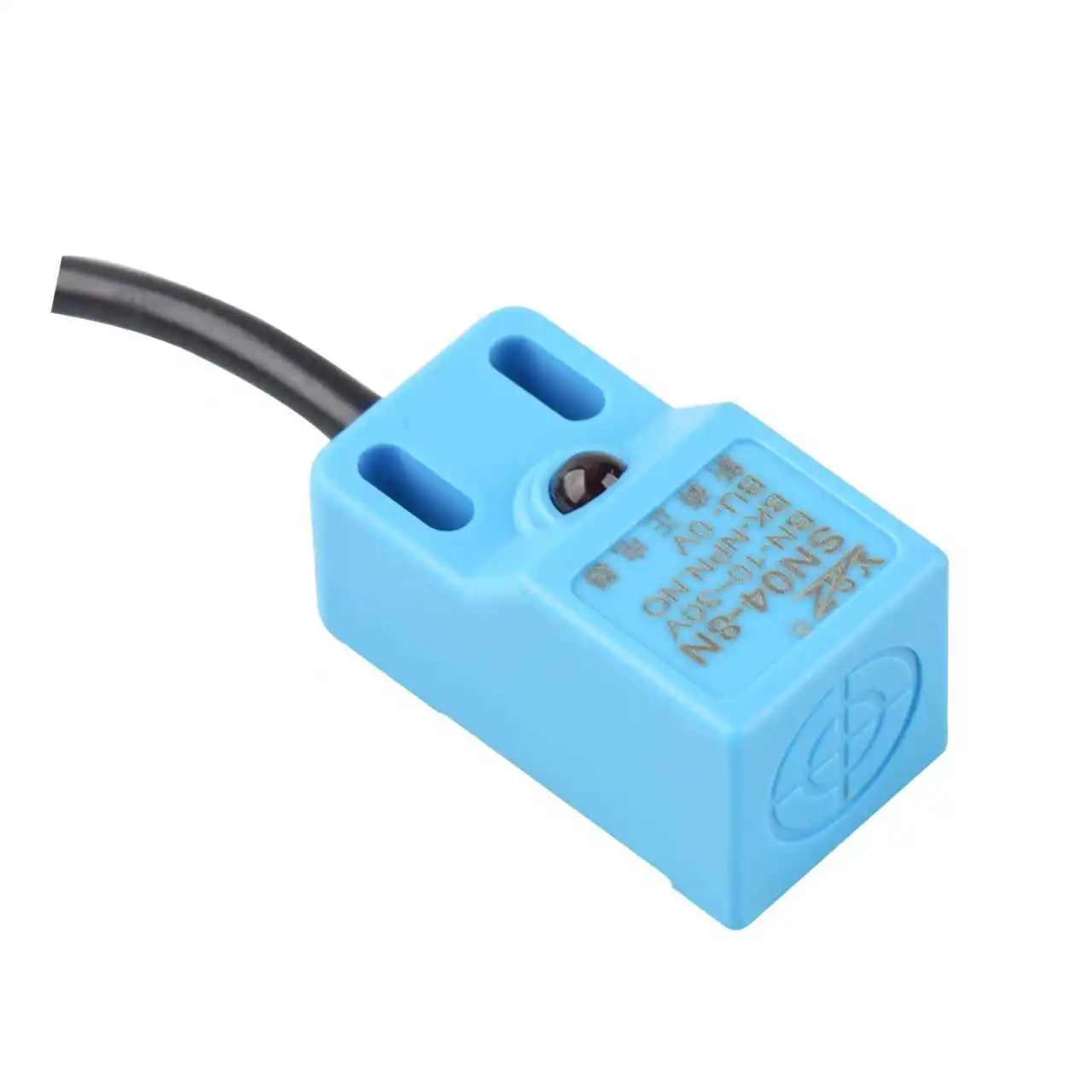
Is this a direct replacement or an engineering change?
“Equivalent” should describe a documented match to the application, not a shared diameter or connector. Separate the replacement into one of these three situations before purchasing.
| Situation | What still needs checking | Next step |
|---|---|---|
| Same exact model | Revision, delivered suffix, stored configuration and the original cause of failure. | Restore the accepted setup and complete the machine’s replacement checks. |
| Different model or brand | Electrical behavior, installation drawing, actual-target detection, timing and environmental limits. | Resolve differences in writing, then run a controlled application trial. |
| Changed wiring, logic, bracket or sensing method | The effect on the machine function, drawings, software and any safety-related interfaces. | Use engineering change control; do not label it a drop-in replacement. |
A supplier cross-reference is a useful starting point. Ask which exact old and new order codes it covers and what exceptions apply. An unresolved critical specification means not approved yet, even when a sample appears to work.
Will the replacement produce the signal your PLC expects?
Check the sensor and input module as a pair. Supply voltage, output topology, switching logic and pin assignment are separate questions; matching one does not establish the others.
Match output topology and switching logic separately
For conventional DC switching outputs, PNP sources current to the load; NPN sinks it. NO/NC describes when the switching output operates, not whether it is PNP or NPN. Photoelectric sensors may instead specify light-on or dark-on operation. Write down the required behavior for target present and target absent, then check the PLC input state in both conditions.
| Check | Compare against the installed circuit |
|---|---|
| Power supply | AC or DC, permitted voltage range, current demand and voltage available at the sensor under operating conditions. |
| Output and input | PNP, NPN, push-pull, relay, two-wire, analog or digital communication; input common and manufacturer wiring diagram. |
| Connector and cable | Pin count, coding, pin functions, cable wiring and any teach or communication pin. Do not transfer a pin map from another product. |
| ON/OFF electrical limits | Output load rating, ON-state residual voltage and OFF-state leakage against the input module’s thresholds. Check minimum load requirements where specified. |
| Measurement signal | Measurement range, units, output scaling, fault indication and PLC conversion—not only “4–20 mA” or “0–10 V.” |
Two-wire sensors need particular attention because their operating current flows through the load circuit. Leakage can prevent a load from recognizing OFF. Use the exact sensor and input-module specifications; do not add a resistor or adapter as an unreviewed workaround.
How can two 4–20 mA sensors report different values?
Illustrative calculation—not a customer test. Assume the old pressure sensor maps 0–10 bar to 4–20 mA. A proposed replacement maps 0–16 bar to the same output. Both mappings are linear, and the PLC still uses the old scale.
- At a real pressure of 5 bar, the old sensor outputs 12 mA.
- The replacement outputs 9 mA: 4 + 16 × (5 ÷ 16).
- The unchanged PLC displays 3.125 bar: (9 − 4) ÷ 16 × 10.
The connector and signal type match, but the measurement does not. Use the correct range or an approved scaling change, then verify known input values and the documented fault behavior before release.
Can a sensor fit the bracket but detect differently?
Yes. Mechanical fit only proves that the part can be mounted. It does not establish the same sensing-face position, target response or operating margin.
Check the sensing face—not only the housing diameter
Compare the dimensioned drawings: usable thread, body length, mounting slots, face direction, cable exit and connector clearance. A longer body can move the sensing face or leave insufficient room for the mating cable.
For inductive sensors, flush and non-flush mounting requirements matter. A non-flush sensor installed too close to surrounding metal can be pre-damped. Follow the exact model’s metal-clearance and adjacent-sensor spacing drawings rather than applying a universal spacing multiplier.
What can change within one sensor family?
OMRON’s E2E NEXT lineup lists these shielded, three-wire, M8-body models with a 4 mm sensing distance and M12 connection. Their shared family and range do not make them interchangeable.
| Exact order code | Listed output / IO-Link | Listed body size |
|---|---|---|
| E2E-X4B1T8-M1 | PNP, NO; IO-Link COM3 | 43 mm |
| E2E-X4C18-M1 | NPN, NO; no IO-Link | 43 mm |
| E2E-X4B1TL8-M1 | PNP, NO; IO-Link COM3 | 53 mm |
The second model changes the electrical interface; the third changes body size. IO-Link can also change the listed NO operation to NC on supported models, so verify the actual configuration. Source: OMRON E2E NEXT lineup and footnotes.
Test the real target and the unwanted background
Catalog distance is not a guarantee for every object. An inductive sensor’s response depends on the target and installation; optical sensors also depend on the light path, surface and background. A capacitive application may change with the target, container and surrounding material.
Keep the application’s actual sensing method in view. A diffuse sensor uses light returned by the target; a through-beam pair detects interruption between separate units; a retro-reflective arrangement needs the specified reflector. Similar housings do not make these methods substitutes.
Compare both the required detection condition and the nearest unwanted object. Include the smallest target, worst position, normal vibration, surface variation and expected contamination. A candidate that detects the target but also detects the bracket or background has not passed.
Match environmental exposure, not just the IP number
Check the actual temperature, cleaning process, chemicals, oil or coolant, vibration and cable movement. A housing ingress rating does not by itself establish chemical resistance or continuous-flex cable suitability. Verify connector sealing and accessory ratings as part of the installed assembly.
What must you restore on an IO-Link or teachable sensor?
The same hardware can behave differently after a reset or replacement. Restore the accepted switching threshold, hysteresis, light-on/dark-on or NO/NC logic, filters, delays, measurement units and output assignment where those settings exist.
An IODD describes an IO-Link device and its data and parameters; it is not the saved configuration of your machine. Keep the accepted parameter values and device identification together.
Check which parameter set the master will restore
Automatic replacement depends on compatible device identity, supported data storage and the master’s configured backup/restore mode. A replacement may otherwise be rejected or receive an older stored setup.
SICK’s IO-Link device replacement guidance explains that vendor/device identification is checked and that some parameter changes are not automatically backed up. Confirm the backup represents the last approved setup, not merely the last available file.
After restoration, verify the process-data mapping, units, status information and switching behavior in the PLC. Successful communication alone is not proof that the application parameters are correct.
What must a replacement test prove before production restarts?
Define acceptance conditions before the trial. “The LED switches” is not enough: the intended target must produce the expected input and machine response, while the no-target condition must remain correctly recognized.
After isolated installation and wiring checks, qualified personnel should use the machine’s controlled test and restart procedure. Begin with a controlled functional check, then cover the approved operating envelope. Do not create unsafe faults or bypass guards to complete a test.
| Test condition | Required result | Record |
|---|---|---|
| Target present and absent | Sensor output and PLC input agree with the documented state logic. | Physical condition, sensor indication, input state and resulting machine action. |
| Position and target variation | Reliable detection throughout the required window, without detecting the unwanted background. | Target samples, approach direction, mounting gap and worst positions tested. |
| Production speed and spacing | Each required event reaches the controller without missed or duplicate events. | Speed, part spacing, observed pulse duration and input/filter settings where relevant. |
| Restart and diagnostics | Accepted settings return and the control system handles documented startup and fault states correctly. | Restart behavior, restored parameters and permitted diagnostic checks. |
| Expected operating exposure | Detection remains stable under the specified production conditions. | Temperature, contamination, vibration or cleaning conditions actually covered; list exclusions. |
Separate sensor response from controller timing
A sensor can switch correctly while the PLC misses a short pulse. Check the sensor response together with target dwell time, input filtering, input-module update behavior and the program’s handling of the signal. Switching frequency is not a substitute for reviewing that whole timing path.
Safety-related replacements need a separate approval path. Ordinary industrial sensors must not replace protective devices simply because they detect the same object. For light curtains or other safety-related sensing, follow the machine manufacturer’s requirements and applicable safety validation process. Matching physical fit or a Type designation alone is not sufficient.
What should you document before approving the new spare?
Keep one traceable replacement record: old and new full order codes, relevant revisions, supplier documents, changed wiring or brackets, accepted parameter file, trial conditions, results and the responsible approver. Record limitations explicitly; a dry, stationary bench test does not prove performance on a wet, vibrating production line.
If a supplier proposes an alternative, send the old label and installation photographs, machine function, target sample or specification, input-module details and required operating conditions. Request an exact-model datasheet, connection diagram, dimensioned drawing and written explanation of any differences.
Approve the application, then standardize the spare. Update the machine documentation and spare-parts list only after the relevant checks pass. If a critical difference remains unresolved, obtain the missing evidence or use the approved original part rather than treating uncertainty as compatibility.
Sources and method references
- OMRON E2E NEXT lineup — exact order codes, output variants, IO-Link support and listed body sizes in the comparison.
- OMRON proximity sensor precautions — target effects, surrounding metal, interference and leakage-current considerations.
- ifm inductive sensor installation guidelines — flush/non-flush mounting and pre-damping.
- OMRON photoelectric sensor introduction — through-beam, retro-reflective and diffuse sensing arrangements.
- SICK: IO-Link device replacement / data storage — identity checks, backup/restore modes and stored parameters.
- ifm IO-Link technology overview — IODD, device identification and parameter data.
- HSE machinery maintenance guidance — competent maintenance, isolation and controlled work.
The pressure example is an ideal linear-scaling calculation, not measured performance. The model comparison illustrates specification differences; it does not establish an approved substitute. Use the delivered model’s documentation and the machine’s acceptance requirements.