
Sensors for Food Packaging Machines: How to Choose by Task
Choose food packaging sensors by the event they must detect: package presence, a printed mark, material level or a machine position. Then match the sensing path, line timing and cleaning exposure. A reliable trigger helps control the machine; it does not automatically prove correct fill quantity, seal integrity or label content.
Which sensor should you start with at each packaging station?
Start with the event the machine needs to recognize, then choose a sensing method that can distinguish that event from normal variation. A carton arriving, a printed mark passing and a package meeting its weight specification are different jobs—even when they happen on the same conveyor.
| Required event | Useful starting method | Decisive check |
|---|---|---|
| Tray, pouch or carton arrives | Through-beam, retro-reflective or background-suppression photoelectric sensing. | Can the target and the smallest gap produce distinct signals in the available mounting space? |
| Clear bottle or transparent tray arrives | A dedicated transparent-object optical sensor; suitable ultrasonic sensing where geometry permits. | Test the clearest area, curvature, empty/filled states, moisture and minimum spacing. |
| Registration mark passes the reading point | Contrast or registration-mark sensor. | Actual printed film, spot orientation, working distance and captured pulse at line speed. |
| Film roll runs low or the web breaks | Ultrasonic distance sensing for roll diameter; appropriate optical or ultrasonic web detection. | Roll edges, guide rollers, near-range limits and changing web position. |
| Metal stop, jaw or mechanism reaches a position | Inductive proximity sensing; other position sensing where required by the mechanism. | The actual metal target, approach direction, clearance and temperature—not the packaged food. |
| Fill, label or finished package passes inspection | A defined level measurement, checkweigher, code reader, vision or other defect-specific inspection system. | Does the measurement prove the required quality characteristic, rather than merely detect presence? |
When access is tight, a fiber optic head can bring a small sensing point into the machine while keeping its amplifier accessible. It still needs the right optical mode, signal margin, bend radius and environmental rating; a small head does not automatically solve transparent-film detection.
Keep personnel protection separate. Ordinary packaging presence, contrast and position sensors are not substitutes for a validated machine-safety function. Select guarding and safety devices through the machine risk assessment. Isolate hazardous energy before repositioning sensors or accessing moving mechanisms.
How do you detect clear, glossy or changing packages reliably?
Choose the sensing path before adjusting sensitivity. Reliability depends on a stable difference between “target present” and “target absent,” not simply on obtaining one successful switch with a clean sample.
Use beam interruption when the package reliably blocks the path
For an opaque carton or pouch, through-beam sensing is a practical starting point when an emitter and receiver can be mounted on opposite sides. Retro-reflective sensing uses a reflector on the far side and wiring on only the sensor side. Check guide rails, holes in the package, seams and the smallest gap between adjacent items.
For shiny opaque packages, polarized retro-reflective sensing can help distinguish the intended reflector return from some direct target reflections. That does not make every polarized model suitable for clear plastic: transparent-object capability is a separate specification.
Use one-sided sensing only with a dependable target return
Diffuse sensing receives light reflected by the package itself. Background suppression adds distance discrimination so a rear surface can be ignored within the model’s limits. It is useful when there is no space for opposite-side equipment, but color, curvature, gloss and distance still matter. Test the darkest finish at the farthest position as well as the brightest finish near the background.
A standard background-suppression sensor is not automatically a clear-tray sensor. Dedicated transparent-object designs may use a reflector or a specifically taught background. Follow the optical arrangement documented for that product; these methods are not interchangeable.
Test the package throughout its production states
A clear container changes optically when it is filled, labeled, chilled or covered in condensation. Include the transparent wall, label edge, rib and seam in testing. A method that works only when a label crosses the beam may fail before labeling or on a different package size.
Illustrative example: a tray change exposes the wrong target. Suppose a detector works on an opaque tray but misses a new clear tray. It switches again once the tray is filled. That suggests the contents may be providing the useful signal; it does not demonstrate reliable empty-tray detection. Test empty and filled trays separately in the final geometry. If the filling station must confirm an empty tray, change the sensing arrangement until that state is independently detectable.
Ultrasonic sensing is worth evaluating when optical properties vary, especially for roll diameter or web presence. It has its own beam geometry, near-range and timing limits. Pepperl+Fuchs’ roll-monitoring application, for example, describes adjustable sound beams to avoid spool edges and synchronization to manage neighboring sensors. It is evidence for that arrangement, not a universal minimum roll width.
What makes print-mark detection accurate at production speed?
The sensor must resolve the intended mark against its background, and the controller must capture the correct transition. Final cut or seal position also depends on web motion, encoder information, control logic and mechanical response.
Teach the finished material, not a printed screenshot
Use production film with its ink, laminate and backing condition. Keep the mark inside the light spot’s intended path throughout web wander and flutter. Confirm both spot dimensions, their orientation to travel, the working distance and the manufacturer’s mounting guidance for reflective material.
For registration, “color mark” usually means detecting a contrast transition. A device that selects an illumination color does not necessarily identify the correct product artwork or read a lot code. Those are separate inspection tasks.
A documented example: teaching speed is not the same as running speed. Banner’s R58E manual, revision F, specifies a Dynamic TEACH condition in which a mark covers the 1.2 mm sensing-image dimension for at least 0.002 seconds. Its 5 mm mark example gives (5 − 1.2) ÷ 0.002 = 1,900 mm/s, or 114 m/min. This is a model-specific teaching limit under the stated orientation—not a universal packaging speed or a guarantee that a PLC will capture every mark. See the R58E manual, page 5.
Verify pulse capture separately from position accuracy
Check the shortest actual output pulse and the OFF gap at maximum speed against the input module’s filtering and capture requirements. A pulse may be present at the sensor yet never reach the machine program. Conversely, every pulse may be captured while cuts still shift because of film slip, stretch or variable actuator timing.
Do not treat switching frequency as a complete timing budget or calculate an approval margin by simply adding all advertised delays. Document the active sensor settings, input mode and signal path. Judge the finished cut or seal position at the machine, not from the sensor LED alone.
Can one sensor verify fill quantity, seal integrity and the correct label?
Not from a single presence signal. Define the characteristic that must pass, then choose a measurement that can reveal its failure. A sensor can provide a useful machine interlock without proving the finished package is acceptable.
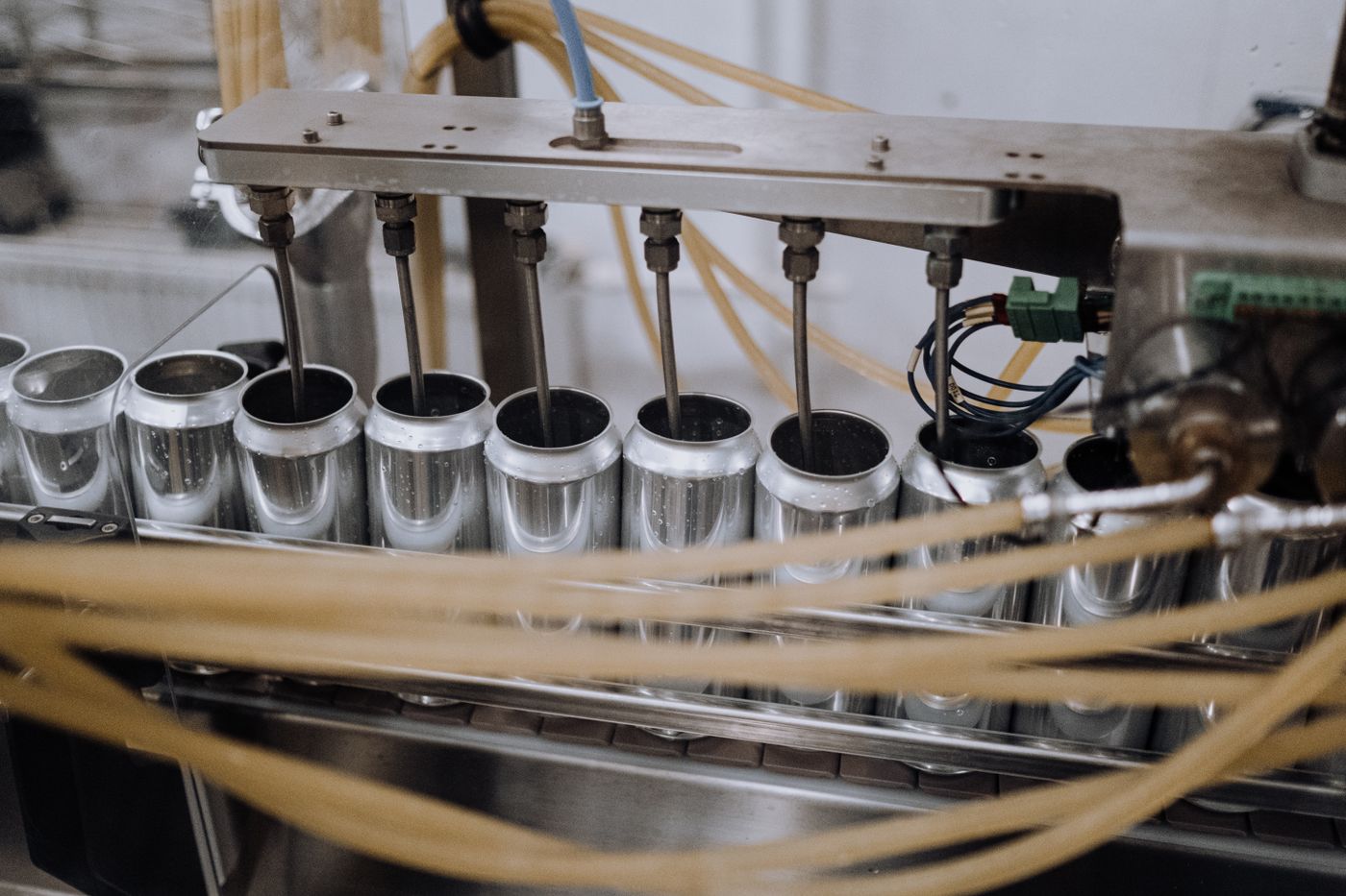
Level is not the same as net weight
A point-level sensor can indicate that material has reached a particular height. Capacitive sensing through a suitable non-metal wall may be an option, but the wall, product, residue and moisture all influence the result. Foam and changes in product density can also make visible fill height a poor substitute for quantity.
When the acceptance requirement is package weight, evaluate weighing under the actual conveyor and product conditions. Account for packaging tare if the required result is net contents. Do not approve an optical or capacitive level switch as a weight check simply because the packages look equally full.
Jaw position is not proof of a sound seal
A position sensor can confirm that a mechanism reached its expected location. Temperature, force or pressure measurements monitor other process conditions. None alone proves that the seal is free from trapped product, wrinkles, channels or leaks.
Choose an inspection method against the defined defect. Vision can inspect accessible visual features; hidden defects or a leak-tightness requirement may need another validated test. Specify the smallest relevant defect and its possible locations before selecting equipment.
Label presence is not label correctness
A photoelectric sensor may confirm that something occupies a label position. Checking the correct SKU, readable code or printed date requires an appropriate reader or vision task, expected data and a reject decision. METTLER TOLEDO’s flow-wrap inspection guide separates weight control from label-data inspection—a useful distinction when writing the station specification.
What must a washdown sensor specification include beyond its IP rating?
Specify the cleaning exposure and the complete installed assembly. An enclosure rating addresses a defined protection test; it does not by itself establish resistance to every cleaning chemical, hygienic cleanability or suitability for food contact.
Describe the actual location and cleaning cycle
A sensor on a dry case packer has a different exposure from one beside an open filler or in a washdown area. Record the cleaning agent, concentration, temperature, pressure, duration and frequency, plus condensation and operating temperature. Give the supplier these conditions rather than asking only for a “waterproof food sensor.”
For a claimed IP69 or IP69K rating, request the exact applicable standard and test conditions. Do not assume similar-looking rating labels cover the same exposure or that one rating automatically establishes another. The public scope of IEC 60529 concerns enclosure protection; cleaning-chemical compatibility needs separate evidence.
Include the connection, mounting and cleanability
Check the lens, seals, cable jacket, mating connector and mounting hardware, not just the metal housing. Obtain the conditions needed to retain the rating—such as the specified mating connector and assembly instructions. Stainless steel alone does not prove compatibility with the cleaning regime.
Where hygienic requirements apply, assess residue traps, exposed threads, drainage and access for cleaning. EHEDG Document 37’s public scope explicitly treats hygienic integration as important alongside the sensor itself. A suitable component can still be installed in a way that is difficult to clean.
How do you prevent missed triggers and incorrect rejects?
Follow the event from the package to the final action. This separates an optical problem from an electrical, control or mechanical problem and avoids replacing a sensor that is already switching correctly.
- Physical eventThe intended package feature reaches the sensing point.
- Sensor outputOne intended transition occurs, with a usable pulse and gap.
- Controller captureThe input recognizes the correct state and edge.
- Package trackingThe inspection result stays associated with the right package.
- Machine actionThe correct package is processed or rejected, and the outcome is confirmed.
Match the electrical interface and the event logic
Confirm supply range, connector pinout, NPN/PNP output and input common from the actual devices. Then check light-on/dark-on or NO/NC behavior separately. Define what the program should do when a package is absent, the beam remains blocked, a signal is missing or a recipe changes.
Use appropriate electrical measurement and controller diagnostics; an indicator LED is not a record of a short pulse. Electrical work and moving-machine tests must follow the site’s authorized procedures.
Check tracking when the correct detection leads to the wrong action
For example, a missed-label result may be captured correctly but reject the following package after conveyor speed or spacing changes. In that illustrative situation, investigate event-to-package association, encoder or delay logic, transport slip and actuator response before changing sensitivity. A “reject command issued” bit is not evidence that the intended item reached the reject bin.
IO-Link is useful when the selected device provides needed diagnostics or controlled recipe parameters. Confirm those functions in its IODD and master configuration. It is not automatically a faster trigger path; choose and validate the event interface separately from the parameter-setting interface.
What should a production trial prove before the sensor is released?
It should show that the required event remains distinguishable across the agreed operating range—and that the machine acts on it correctly. Set acceptance criteria before testing; a few clean samples at low speed are not a substitute for the intended production conditions.
| Challenge | Evidence to record |
|---|---|
| Package and recipe variation | Accepted and rejected samples for each relevant material, color, size, fill state and printed design. |
| Speed and spacing | Missed or extra events at minimum gaps, operating speeds and permitted start/stop transitions; final positional error where relevant. |
| Mounting and environment | Behavior over permitted position variation and after the defined cleaning/drying cycle; any loss of signal margin. |
| Inspection and rejection | Known defects detected, good products rejected incorrectly, and confirmation that the correct items were removed. |
| Changeover and recovery | Correct recipe restoration, power-cycle behavior and documented response to signal loss or blocked detection. |
Use a controlled test plan approved for the machine; do not introduce hazardous jams or bypass guarding. Record sample counts and conditions with the results. Zero failures in a limited trial describes that trial, not a guaranteed failure-free production rate.
For a useful supplier review, send real package samples, the required event, a dimensioned mounting view, line speed and minimum gap, controller input details and the cleaning regime. Ask for a named sensor/head/reflector/cordset combination with its settings and unresolved limitations. Those details turn a family recommendation into a testable selection.
Sources and method references
- SICK — ClearSens: transparent-object sensing for plastic packaging, glass and film; product-specific methods.
- OMRON — Photoelectric sensing methods and polarized retro-reflective sensing: optical paths, background suppression and reflective targets.
- Pepperl+Fuchs — Roll diameter and web-break detection: sound-beam selection, unwanted reflections and adjacent sensors.
- Banner — R58E manual, 122928 Rev. F: mounting, spot dimensions, Dynamic TEACH and output configuration. The numerical example above applies only to its stated teaching conditions.
- METTLER TOLEDO — Flow-wrap inspection: separate weight, labeling and product-inspection tasks.
- IEC 60529 consolidated edition 2.2 and EHEDG Document 37 public scope: enclosure protection and hygienic sensor integration, respectively.
- IO-Link Community — Technology: point-to-point communication, diagnostics, parameterization and IODD.
- ifm — Capacitive sensing technology: through-wall level sensing, target properties and installation conditions.
- HSE — Maintenance of work equipment: competent maintenance, isolation and stored-energy precautions.
Manufacturer examples describe their named products, not equivalent specifications for all sensors. Scenarios labeled illustrative explain selection reasoning; they are not customer test reports.