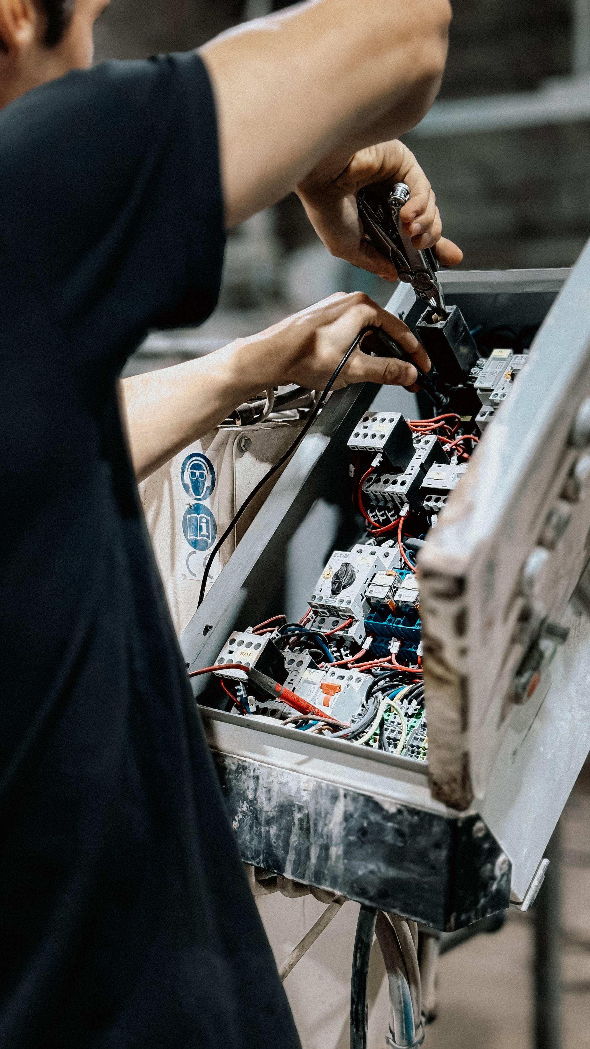
Industrial sensor wiring guide
Sensor Cable Length: Calculate the Run Before You Order
There is no universal maximum sensor cable length. The usable run is the shortest limit set by the exact sensor, interface, voltage or loop budget, cable construction, EMC conditions, and mechanical duty. This guide turns those variables into an order-ready cable plan.
- Switching, analog, IO-Link, and RS-485
- Voltage drop and 4-20 mA loop budget
- Shielding, connectors, and continuous flex
Start with the exact datasheet and approved extension method.
Calculate round-trip resistance, current, and voltage headroom.
Match the interface, cable, topology, shielding, and termination.
Separate fixed routing from occasional flex and continuous motion.
The direct answer
How long can a sensor cable be?
A sensor cable can be only as long as the complete sensing system allows. A 30 m cable can be routine for one 4-20 mA transmitter yet unreliable for another device with a different supply requirement, conductor size, receiver load, or route. A 20 m run can comply with an interface rule but still fail because excessive voltage drop leaves the sensor below its operating voltage.
Do not begin with a generic distance chart. Begin with the sensor model and its output: 2-wire switch, 3-wire PNP or NPN, 0-10 V, 4-20 mA, IO-Link, RS-485, RTD, thermocouple, or another dedicated interface. Then calculate the electrical budget and confirm that the proposed cable is approved for the route.
The approved cable length is the lowest result from the manufacturer limit, electrical calculation, signal or protocol limit, and mechanical or environmental requirement.
For a new sensor application, define the full route rather than the machine's straight-line dimension. Include cabinet entry, vertical drops, service loops, articulated sections, junction boxes, and the final connector position. Keep a sensible installation allowance, but do not hide an uncertain route inside a large arbitrary percentage.

One number is not enough
Four independent limits decide the usable cable length
A cable run is acceptable only when it passes all four checks. Improving one condition does not cancel a limit in another.
Sensor and interface specification
The sensor head, amplifier, output circuit, protocol, connector, and vendor-approved accessories can set a hard system limit. A separate-amplifier sensor may be sensitive to cable capacitance in a way that a built-in-amplifier switch is not.
Voltage or loop-load budget
Longer conductors add resistance. The resulting voltage drop depends on current and the full outgoing and return path. For current loops, the receiver, barriers, indicators, and wiring all consume supply headroom.
Signal integrity and EMC
Cable capacitance, impedance, data rate, topology, termination, switching noise, common-mode voltage, and ground potential can limit a run before DC voltage drop becomes critical.
Mechanical and environmental rating
A cable suitable for fixed installation may fail in a drag chain. Temperature, oil, coolant, washdown, abrasion, torsion, bend radius, and ingress protection determine the required cable family and accessories.
Choose by interface
What changes with each sensor output?
These are engineering checks, not universal distance promises. The exact product documentation remains the controlling source.
Voltage at the sensor and voltage delivered to the PLC input.
Confirm both ON and OFF states at worst-case voltage and temperature.
Evaluate accuracy and noise at the receiving input, not supply drop alone.
Calculate at 20 mA and the lowest expected supply voltage.
Also confirm device current and voltage drop through every cordset.
Verify transceivers, baud rate, cable, grounding, and node layout together.
Follow both the sensor and acquisition-system documentation.
Planning calculator
Estimate cable voltage drop and remaining headroom
Use the lowest supply voltage and highest normal current. For a 4-20 mA loop, enter 20 mA and include the receiver, barrier, display, and other series loads in the external drop field.
Estimated result
Positive electrical headroom. Continue with device, signal, EMC, and mechanical checks.
Planning estimate only. It does not override a manufacturer or protocol limit and does not model capacitance, transient noise, common-mode voltage, connector derating, or temperature rise unless included in your input data.
Round-trip resistance = 2 x one-way length x conductor resistance per unit length. Use the resistance at operating temperature when available.
Cable voltage drop = circuit current x round-trip resistance. Use worst-case current, not the average process value.
Headroom = supply voltage - device minimum - external series drop - cable drop. Keep a documented design reserve for real operating variation.
The sensor's supply conductors and its voltage-output signal path are related but not identical problems. For the analog signal, evaluate output impedance, receiver input impedance, return-path voltage, cable capacitance, bandwidth, shielding, and noise at the receiving terminal.
Worked example
Example: checking a 100 m, 4-20 mA transmitter loop
Assume an illustrative 24 VDC source, a transmitter that needs at least 10 V, a PLC input and barriers that together consume 5 V, a 100 m one-way cable, and conductors specified at 55 ohm/km. At 20 mA, the outgoing and return conductors total 200 m and approximately 11 ohm. The cable drop is about 0.22 V.
The remaining headroom is 24 - 10 - 5 - 0.22 = 8.78 V. That result passes this simplified electrical check, but it does not declare the installation approved. The designer must still check the transmitter's exact load curve, minimum power-supply tolerance, intrinsic-safety barriers if present, surge protection, connector resistance, cable temperature, shield method, and route.
A current loop does not have a universal cable-distance number. Its electrical limit is calculated from available loop voltage and total series resistance, then reduced further by product, environmental, and installation constraints.
Analog runs
0-10 V and 4-20 mA solve different cable problems
Both interfaces can work well when designed correctly. The right choice depends on distance, accuracy, noise, diagnostics, control hardware, and the sensor options available.
Voltage output: protect the measured voltage
A voltage input reads the potential difference between signal and reference. Small unwanted voltage on either path can become measurement error.
- Confirm sensor output impedance and PLC input impedance.
- Use a dedicated signal return where the design requires it.
- Evaluate cable capacitance against bandwidth and output stability.
- Keep the pair away from VFD, motor, contactor, and heater conductors.
- Measure noise and offset at the receiver under full machine operation.
Current loop: protect voltage headroom
The receiver measures loop current. Cable resistance mainly consumes available voltage, so the design is governed by the complete loop-load budget.
- Calculate at 20 mA and the lowest source voltage.
- Include transmitter minimum voltage and receiver burden.
- Add barriers, displays, isolators, surge devices, and wire resistance.
- Confirm polarity and whether the transmitter is loop-powered or separately powered.
- Retain enough reserve for tolerance, temperature, and maintenance changes.
Changing a voltage signal to 4-20 mA can improve a difficult long run, but the converter adds power, accuracy, isolation, environmental, and maintenance requirements. Compare a native current-output sensor with the complete converter solution before ordering.
Digital sensor links
Connector shape does not define the communication limit
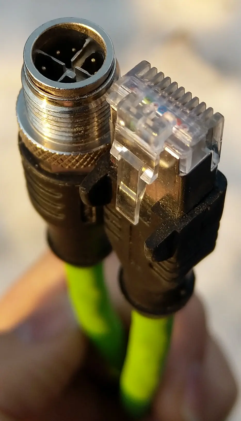
An M12 connector can carry discrete I/O, analog signals, IO-Link, fieldbus, or industrial Ethernet, depending on its coding and the connected equipment. Seeing an M12 connector is not enough to choose a cable or infer a maximum length.
IO-Link
Official IO-Link design guidance specifies a maximum 20 m connection from the master port to the device. Designers must also verify voltage drop and port current, especially with long, small-conductor cordsets or higher-current actuators. Adding an extension that keeps the total below 20 m does not eliminate the electrical check.
RS-485
RS-485 distance is a network-design result, not a fixed promise. Longer runs generally require lower data rates and disciplined cable, topology, termination, biasing, grounding, and surge control. Long stubs, star wiring, incorrect termination, or excessive common-mode voltage can cause intermittent errors even when the total cable length sounds acceptable.
A digital receiver has thresholds and common-mode limits. Cable loss, reflections, ground-potential difference, and transient interference still affect reliable communication.
Route engineering
Good cable routing protects both signal quality and maintenance time
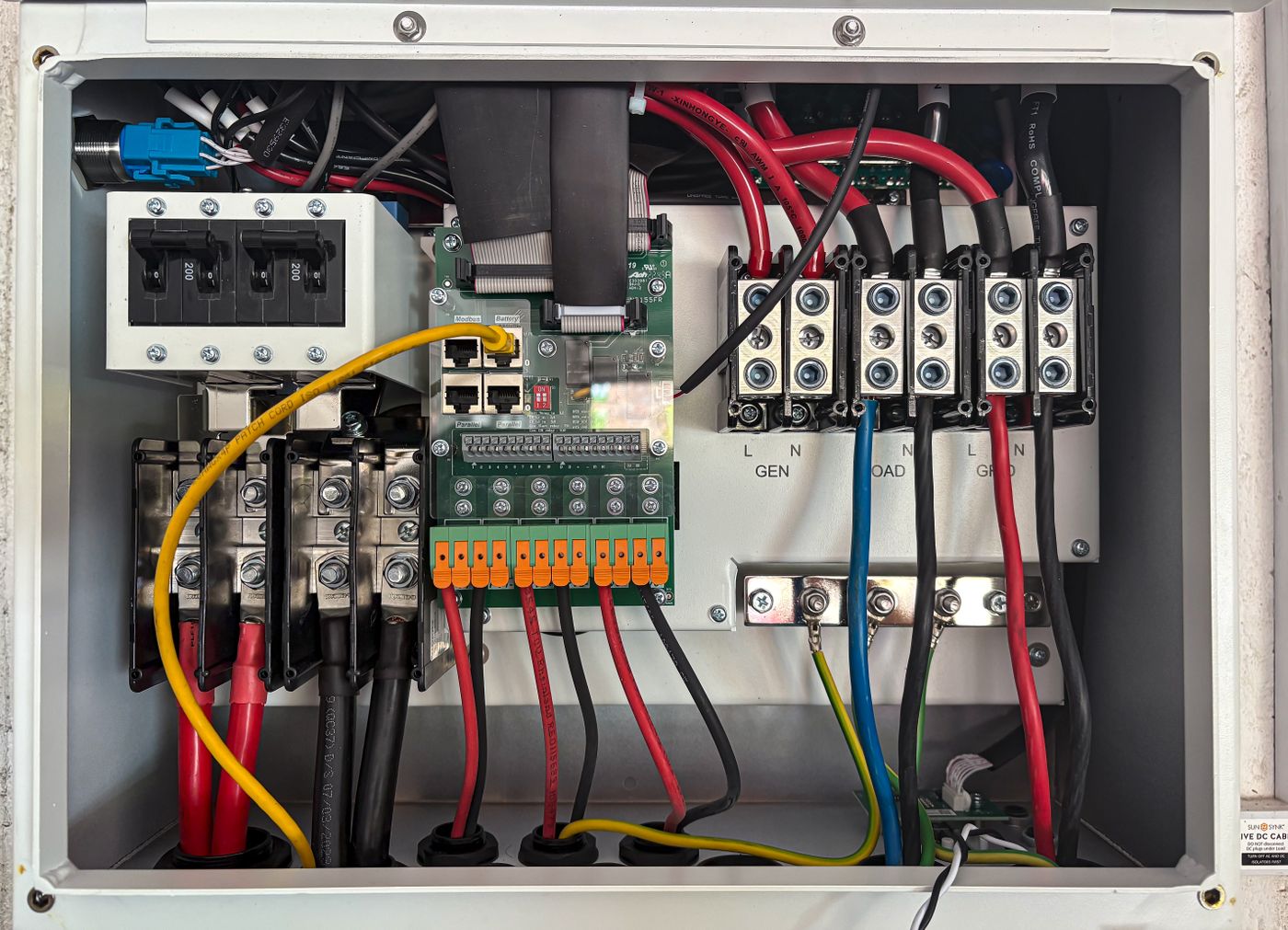
Plan sensor cables as instrumentation, not as leftover wire. Keep sensitive signal and communication cables separated from motor outputs, VFD cables, contactors, braking resistors, transformers, welding conductors, and other high-current switching sources. Where crossings are unavoidable, cross as close to 90 degrees as the installation permits.
Use grounded metallic separation, conduit, tray division, or physical distance according to the machine's applicable electrical and EMC practices. Avoid large uncontrolled service loops near noise sources. Secure the cable so connector strain relief is not carrying the route's weight.
Shielding is a system, not a single rule
A shield works only when the cable, connector, cabinet entry, bonding hardware, and ground strategy form an appropriate path for the interference spectrum. Some low-frequency measurement systems use a single-point shield connection to manage loop current. High-frequency industrial communication often requires low-impedance bonding at both ends with equipotential bonding between cabinets. Follow the device, network, and machine EMC instructions rather than applying "ground one end" to every sensor.
- Terminate shields with short, wide, low-impedance connections where specified.
- Preserve 360-degree shield continuity through suitable connectors and glands.
- Do not use a cable shield as the protective-earth conductor.
- Investigate ground-potential difference before connecting distant cabinets.
Extending a sensor cable
Choose an extension method that preserves the original system
A working splice is not automatically an approved installation. The extension must preserve electrical performance, ingress protection, shielding, strain relief, polarity, and serviceability.
Check the exact manual
Confirm whether the sensor lead may be extended, the maximum permitted length, conductor requirements, and any effect on response time or sensing distance.
Prefer approved cordsets
For connectorized sensors, use compatible coding, pinout, current rating, shield arrangement, temperature class, and environmental protection.
Control every junction
Document pin-to-pin continuity. Use a junction box or field connector rated for the washdown, coolant, oil, dust, vibration, and temperature exposure.
Recalculate the circuit
Add extension resistance, connector resistance, receiver load, and the longest real route. Recheck current capacity and protective-device coordination.
Validate on the machine
Test minimum supply, maximum load, full machine noise, target extremes, motion, warm-up, and fault states before production release.
For some separate-amplifier proximity or photoelectric systems, head-to-amplifier cable capacitance is part of the sensing circuit. Extending that cable can change oscillation, sensitivity, response, or temperature behavior. A general-purpose junction is not a valid substitute unless the manufacturer explicitly approves it.
Mechanical cable life
Fixed, flexing, and torsional routes require different cables
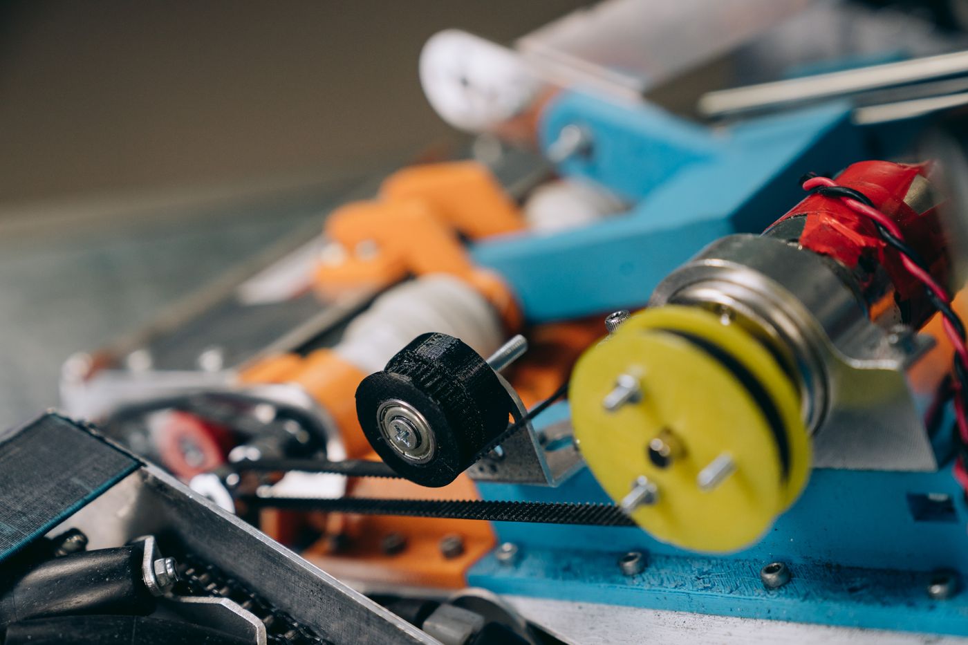
Cable length is only one geometric value. The same 5 m cord can last for years on a fixed frame and fail quickly when repeatedly bent at the sensor exit. Select the cable by motion profile before finalizing the connector and route.
Installed and secured
The cable remains stationary after installation. Respect the manufacturer's minimum fixed bend radius and provide strain relief.
Moved during service
Door, setup, and maintenance movement needs a cable rated for that degree of flexing and a route without sharp hinge points.
Repeated production cycles
Drag chains, robots, and reciprocating axes require dynamic-flex or torsion-rated cable, controlled bend radius, fill, travel, and acceleration.
Protect the transition points
Keep motion away from rigid connector backshells, molded sensor exits, glands, splices, and heat-shrink transitions. Clamp the cable at the points specified by the connector and chain manufacturer. A longer service loop is not automatically safer; uncontrolled loops can whip, rub, or tighten below the permitted radius.
Field diagnosis
How to tell whether cable length is part of the fault
Do not shorten the cable first and call the problem solved. Capture the symptom, measure the circuit, and separate voltage, signal, EMC, connector, and motion failures.
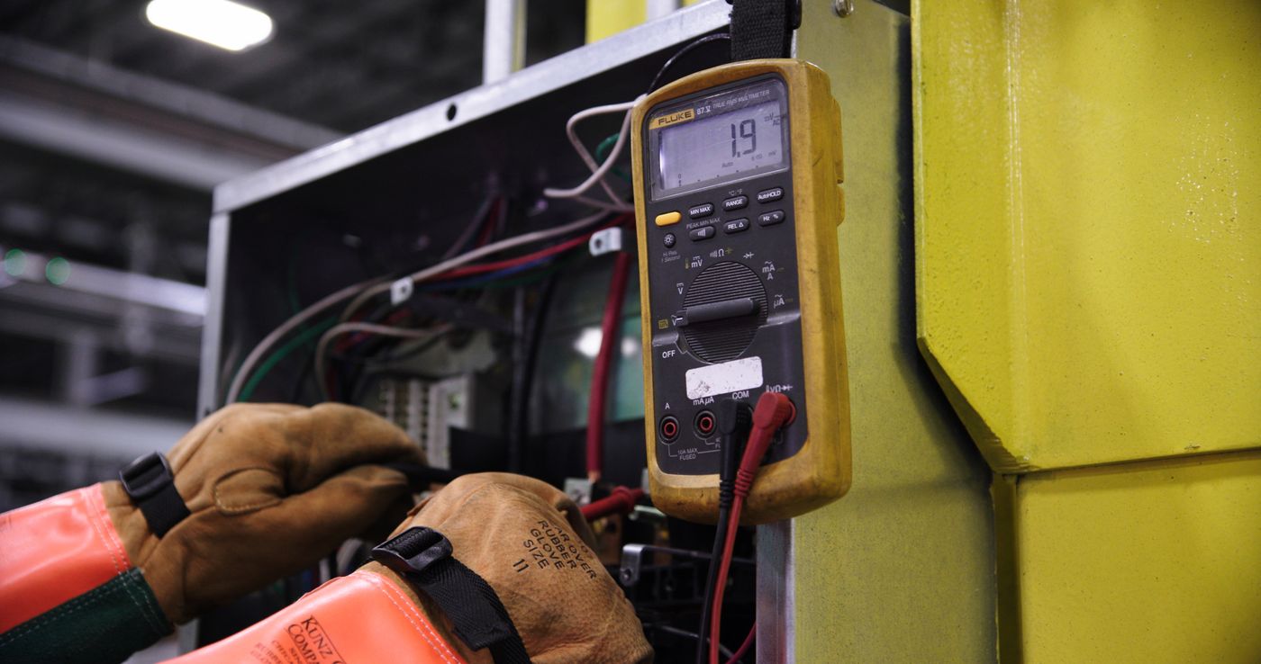
Start with three measurements
- Measure voltage at the source and at the sensor under maximum load.
- Measure the output at the PLC or receiver while the machine is quiet and while motors, valves, heaters, and welders operate.
- Inspect continuity, insulation, shield termination, connector pins, strain relief, and moving sections.
If the symptom appears only during machine motion, inspect flex zones and connectors before changing interface settings. If it appears when a VFD accelerates, compare routing and bonding. If a 2-wire sensor will not turn fully OFF, evaluate leakage current and the PLC input rather than assuming the cable is simply too long.
For a systematic workflow, use the Sensor Troubleshooting Guide and document readings at both ends of the cable.
Before requesting a quotation
Send these details for a cable-length recommendation
A complete application brief lets the sensor manufacturer check the model, output, connector, cable, and route as one system.
Sensing task
Target material and size, sensing distance, response time, mounting space, and required repeatability.
Electrical interface
Supply range, PNP or NPN, NO or NC, analog range, IO-Link port class, RS-485 settings, or specialty input.
Real cable route
One-way length, cabinet and junction locations, service loops, vertical drops, and planned extension points.
Control-side load
PLC input or receiver model, input impedance or burden, barriers, isolators, displays, and available voltage.
Noise environment
VFDs, motors, welding, solenoids, heaters, long parallel power routes, and connections between cabinets.
Mechanical duty
Fixed, occasional flex, drag chain, robot torsion, bend radius, cycles, travel, speed, and acceleration.
Environment
Temperature, oil, coolant, washdown chemicals, UV exposure, abrasion, ingress rating, and hazardous-area needs.
Connection standard
Fixed lead or connector, M8 or M12 size and coding, straight or angled body, shielding, and mating cordset.
Need the sensor and cable checked as one application?
Share the sensor task, interface, one-way route, PLC input, environment, and motion profile. XSZ can help narrow the sensor output, cable construction, connector, and validation checks before ordering.
Continue planning
Related sensor selection guides
Use these pages to confirm the sensing principle and control interface before finalizing cable details.
Browse by sensing family: Proximity Sensors Overview, Photoelectric Sensors Overview, Fiber Optic Sensors Overview, or visit the Sensor Knowledge Center.
Frequently asked questions
Sensor cable length FAQ
Short answers for common ordering and installation decisions.
What is the maximum cable length for an industrial sensor?
There is no universal maximum. Use the lowest limit from the exact sensor manual, interface or protocol, voltage or loop-load calculation, signal-integrity design, and cable's mechanical and environmental rating.
Can I extend a sensor's factory-attached cable?
Only when the manufacturer permits it for that model and the extension preserves conductor size, shielding, capacitance limits, polarity, ingress protection, and strain relief. Separate-amplifier sensor-head cables may have stricter limits because cable capacitance can be part of the sensing circuit.
Is 4-20 mA always better for a long sensor cable?
It is often useful for long industrial runs because wire resistance mainly consumes loop voltage rather than directly scaling the current reading. It still requires a complete voltage and load budget, suitable shielding and grounding, and compatible transmitter and receiver hardware.
How far can a 0-10 V sensor signal travel?
No single distance applies. The acceptable run depends on required accuracy, sensor output impedance, PLC input impedance, return-path voltage, cable capacitance, bandwidth, shielding, routing, and electrical noise. Validate the error at the receiving input under real machine conditions.
Is the IO-Link sensor cable limit 20 m?
Official IO-Link design guidance specifies a maximum 20 m cable between a master port and a device. The installation must also satisfy voltage-drop, device-current, port-class, connector, and environmental requirements.
Should a sensor cable shield be grounded at one end or both ends?
There is no universal answer. Follow the sensor, network, control-system, and machine EMC instructions. Low-frequency measurement systems and high-frequency communication systems can require different shield and bonding strategies, especially between cabinets with possible ground-potential differences.
Can I add several M12 extension cables together?
Only if total length, voltage drop, connector resistance, current rating, interface rule, shield continuity, ingress protection, and mechanical duty remain compliant. Every extra mating pair is another electrical and environmental junction to document and maintain.
How much extra sensor cable should I order?
Measure the real routed path and add only the service and termination allowance required by the installation. Account for cabinet entry, vertical drops, connector approach, maintenance access, and controlled movement. Avoid arbitrary excess that creates tight coils, abrasion, or noise-sensitive loops.
Technical references
Sources used for engineering context
- OMRON: extending proximity-sensor cables
- IO-Link Community: IO-Link Design Guideline
- NI: 4-20 mA current-loop system design fundamentals
- Analog Devices AN-960: RS-485/RS-422 circuit implementation
- Analog Devices AN-1399: long-distance RS-485 design
- LAPP: cable application and bending guidance
- Belden: effective shielding and bonding considerations
Engineering guide updated July 2026. Final values must be confirmed against the exact product, cable, control hardware, and applicable machine standards.