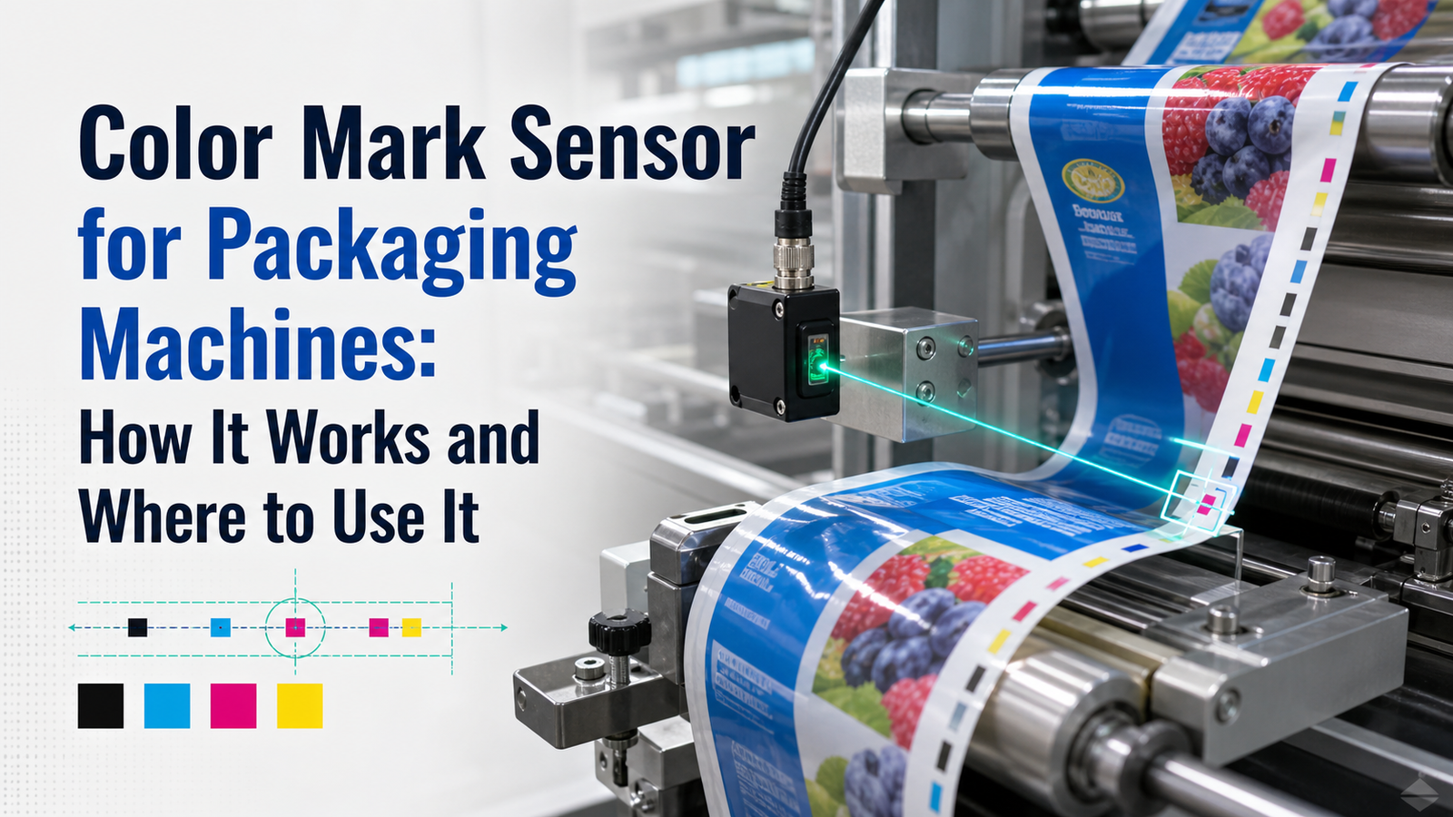
A color mark sensor packaging setup reads printed registration marks on packaging film so machines cut, seal, and fold at exactly the right spot by detecting contrast between the mark and its background. According to Heyi Sensors (2025), EB-S11 color mark sensors on food and coil packaging lines deliver a 100-microsecond reaction time and an 18–28 mm[1] detection distance. This lets them lock onto marks on aluminum foil and polyethylene even at high line speeds, correcting off-center prints and drifting seals.
This guide really answers the questions that buyers actually ask. How does a color mark sensor work? How is it different from a standard photoelectric sensor? What parts make it up? Which packaging jobs actually need one? And which of the specifications, meaning the reaction time, detection distance, and teach mode, should decide the one you pick?
Quick Takeaways
- Color mark sensors detect print marks to trigger cuts within 100 microseconds.
- Typical detection distance runs 18–28 mm[2] on film packaging lines.
- Sensors read mark-background contrast, not true color, for reliable alignment.
- Best for flow-wrap, bag-making, labeling, and foil coil packaging jobs.
- Compare reaction time, RGB LED light source, and teach function before buying.
What’s a color mark sensor and how does it detect registration marks on packaging film?
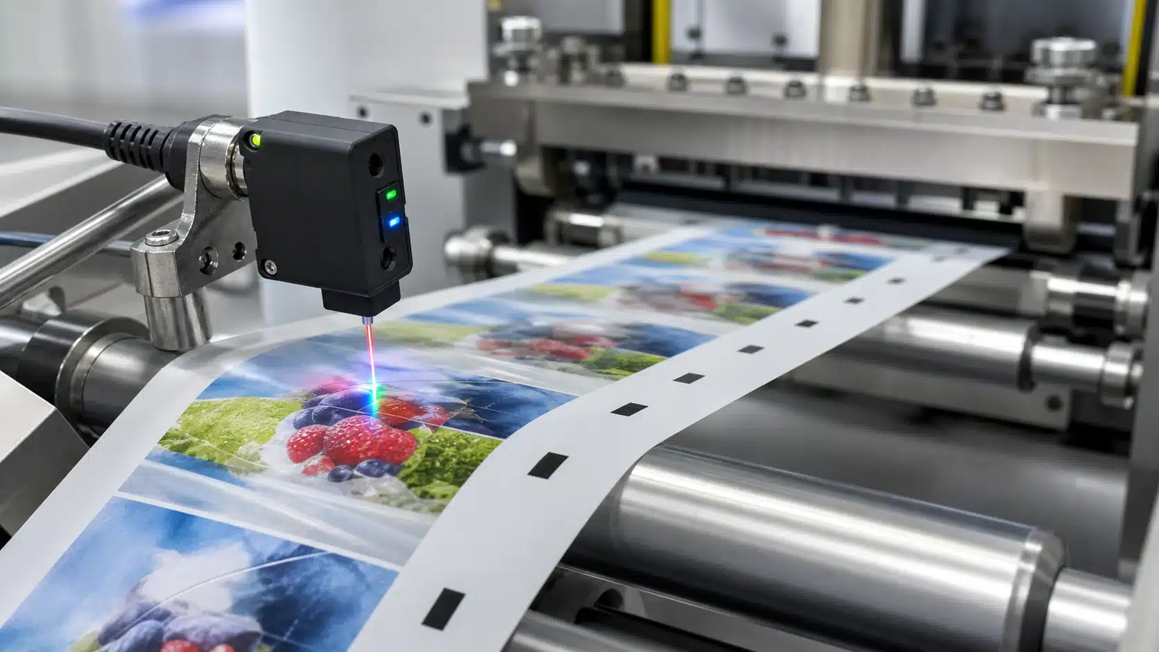
A color mark sensor is basically a light-based device that spots printed registration marks, those small alignment bars that are usually dark or light, sitting on moving packaging film. It reads the contrast in the reflected light, then it sends out an electrical switching signal the moment a mark goes by, which tells the machine to cut, seal, or stop right at the correct spot. Response times get down to 10 microseconds on the faster contrast sensors, so even quickly moving film registers precisely.
At the heart of it, you have an emitter and receiver pair tucked inside a single housing. The emitter throws light onto the film, and that light is often coming from an LED, while the receiver measures how much of it bounces back. A dark registration mark reflects less light than the film surrounding it, and a light mark reflects more. That gap in brightness is the “contrast” that the sensor keys on.
Here is the practical part that most spec sheets skip over. The sensor doesn’t really care about color the way your eye does. What it cares about is the gray-scale contrast between the mark and its background under one specific light wavelength. That is why a red mark on green film can be almost invisible, unless you pick an emitter color that makes the reflected-light gap as wide as possible.
How does the switching signal trigger a machine action?
When the reflected light crosses a set point, the sensor output flips from off to on. That signal goes to a controller or motor drive, which then sets off the cut knife or the seal jaw. In coil and food packaging lines, color mark sensor packaging setups pick up high-contrast black or white lines and fire the cutting mechanism on their own, which cuts down on labor and waste. Detection distances of 18,28 mm keep the sensor safely away from the film without giving up any accuracy.
How does a color mark sensor actually work with RGB and multi-color LED emitters?
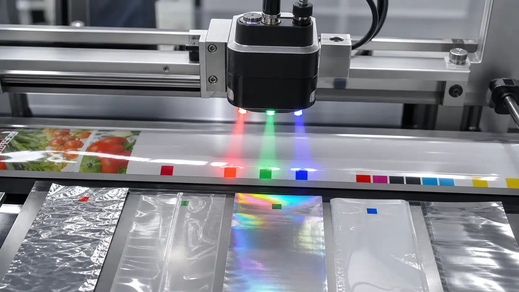
A color mark sensor works by shining a specific LED color at a printed mark, then measuring how much light bounces back versus the surrounding film. Modern units carry switchable red, green, and blue LEDs and auto-pick the wavelength that gives the biggest grayscale gap. The Omron E3S-DC uses a three-element RGB LED source and streams raw RGB data to the host for threshold setting.
The physics is simple. A red mark reflects red light strongly but absorbs green, so a green LED aimed at a red mark on a light background creates a sharp brightness drop the receiver reads as a signal. Pick the wrong color and the mark and background look nearly identical, the reason emitter selection, not sensor price, decides whether a hard-to-read mark triggers at all.
Why does grayscale delta decide reliable detection?
Grayscale delta is the difference in reflected light intensity between mark and background, on a 0,100 scale, and reliable detection depends on it because the sensor triggers only when this contrast crosses a set threshold. A delta above 20 points usually gives stable switching; below 10, you get false triggers from print noise, gloss glare, or film wrinkles.
Practical tip: during teach-in, cycle all three LEDs and lock the one showing the widest delta. On glossy metallic film, blue often beats red because it cuts specular reflection. Speed matters too, a fast sensor reacts in 10 microseconds with 5-microsecond repeatability, tight enough for continuous web packaging running at high line speeds.
Where are color mark sensors used on a packaging line?
Color mark sensors show up in four main places along a packaging line, which are cut-off registration on flow wrappers, label placement, bag-making machines, and pouch sealing. In every one of those spots, the sensor reads a printed eye mark, which is a small reference symbol, and then tells the machine the exact moment to cut, seal, or place the item. A high-speed unit that responds in 20 microseconds, meaning twenty millionths of a second, and runs at a 25 kHz[3] frequency can set off the cutting and sealing action on fast lines without lag.
Flow wrappers: The sensor keeps an eye on the film as it moves along and fires the cross-cut jaw the moment it reaches each mark. This keeps the printed picture centered on every single wrapper, rather than letting it drift a few millimeters off with each bag that goes by.
Bag-making and pouch sealing: A mark sets off the sealing bar so the weld comes down on a blank area of the film instead of landing across the printed text. On coil packaging equipment, the sensors read high-contrast black or white lines to automatically trigger the cutter, which brings down the cost of labor.
How does the sensor sync film travel with the cut position?
The sensor sends a pulse to the PLC or the servo drive the very instant a mark passes by. That pulse resets the indexing counter, so the servo actually knows where the film really is, not just how far it assumes it has traveled. Since film stretches a little and slips now and then, this correction happens on every single cycle. A sensor that reacts in 100 microseconds at a distance of 18,28 mm keeps the print lined up with the cut even when the web is moving at high speed.
This closed-loop timing, where the system constantly checks and corrects itself, is the reason color mark sensor packaging systems hold their registration within tight tolerances instead of slowly building up drift across a full roll.
Why do registration marks get missed on glossy, metallic, and transparent films?
Registration marks get missed on these films because each surface breaks the light-return path that a color mark sensor packaging system depends on. High-gloss film bounces light away, metallic foil scatters it unpredictably, and transparent film gives the mark almost no background to stand out against. All three of these surfaces starve the receiver of the contrast signal it needs to fire.
Why does high-gloss film cause missed marks?
Glossy film reflects light much like a mirror does. This is what’s called specular reflection, where the beam bounces off at the same angle it came in at, so it flies right past the receiver instead of scattering back into it. The sensor essentially sees a black hole even when it’s passing over a printed mark. The way to fix this is by mounting the sensor at a 10,15° tilt, so the mirror bounce misses the lens window while the diffuse light coming off the ink still returns to the sensor.
Why do metallic foils give unstable readings?
Aluminum foil and metallized PET reflect far more light than paper does, and the amount jumps every time the web flutters or the film angle shifts by even a fraction of a degree, which makes the signal spike and then drop between cycles. RGB-based sensors handle this situation better because they read color difference rather than raw brightness, so they stay stable even as production lots change over time.
Why do marks vanish on transparent film?
Clear film offers almost no background contrast at all. Light passes straight through it, so a dark mark and the clear film behind it end up looking nearly identical to the receiver. What you really need here is a mark printed on a colored or white patch, or a background reflector placed behind the web to force a return signal.
How do you choose the right color mark sensor by substrate and print contrast?
Match the sensor feature to the surface, not the price tag. For matte film, a fixed-color LED works fine. Gloss needs a polarizing filter. Metallic and clear film demand RGB auto-teach or background suppression. Choosing by substrate cuts false triggers and keeps your color mark sensor packaging line running without manual threshold tweaks each shift.
💡 Counterintuitive: Color mark sensors don’t actually read color—they detect the contrast between a mark and its background. Evidence: even on shiny aluminum foil and polyethylene, EB-S11 units lock onto dark or light registration bars by comparing reflected light intensity, triggering cuts within 100 microseconds. That’s why a “color” sensor reliably aligns seals regardless of the mark’s true hue, as long as contrast against the film is strong enough.
Which sensor feature wins for each substrate?
Print contrast, the brightness gap between the mark and its background, drives the pick. Low contrast on colored film needs an RGB three-element LED that measures actual color, not just brightness. Some units transmit RGB values to the host so you can set the optimal threshold digitally, as seen on Omron E3S-DC color mark sensors. Gloss reflects the beam back like a mirror, so a polarizing filter blocks that glare. Clear film lets light pass through, so background suppression ignores anything past a set distance.
| Substrate | Main problem | Best feature |
|---|---|---|
| Matte | None major | Fixed-color LED |
| Gloss | Mirror glare | Polarizing filter |
| Metallic | Bright reflection | RGB auto-teach |
| Clear/transparent | Light passes through | Background suppression |
Practical tip: on multi-lot jobs where film color shifts between batches, pick a sensor with a bank function that stores several taught settings. You recall the right one at changeover instead of re-teaching, saving minutes per lot.
How do you mount and teach-in a color mark sensor correctly?

Mount the sensor 15,20° off perpendicular to the film, set the working distance to the sensor’s spec (often 18,28 mm[4]), align the light spot on the mark, then run a two-value teach so it learns mark and background. Tilting the head keeps mirror glare from bouncing straight back into the receiver.
Why does the mounting angle matter on glossy film?
A perpendicular head turns shiny film into a mirror. The reflected beam floods the receiver and washes out the contrast between mark and background. Angling the head 15,20° sends that specular reflection away from the lens. On matte paper, angle matters less, but on gloss or foil it decides whether the color mark sensor on your packaging line reads a clean signal or noise.
Static teach or running-web teach — which do you use?
Use running-web (dynamic) teach whenever you can. Static teach reads the mark while the film sits still, so it never sees the blur and speed effects of real production. Dynamic teach samples both values as the web moves, capturing true contrast at line speed. That matters when reaction time is tight, the TRI-TRONICS COLORMARK II lists a 10-microsecond response with 5-microsecond repeatability, fast enough that even small teach errors shift the trigger point.
Confirm the teach worked. Jog the web through several marks and watch the output LED toggle cleanly on each one. If it flickers between marks, re-teach at a fresh angle.
How does the sensor integrate with PLC and servo registration control?
The sensor sends a fast digital pulse to a PLC input the instant it spots a mark. The PLC pairs that pulse with an encoder count to know exact film position, then commands a servo drive to trim feed length so the print lands on the cut line every cycle. High-speed units like the Heyi EB-WC4 with a 20-microsecond response time and 25 kHz frequency feed detection data straight into the PLC for real-time correction.
What does the signal chain actually look like?
Mark detected → sensor NPN/PNP output flips → PLC high-speed counter latches the encoder value → PLC math compares that value to the target register position → servo adjusts the next feed pull. The encoder is the ruler here. It tracks film travel in tiny increments, so the PLC knows whether the print drifted 0.5 mm early or late and shortens or lengthens the pull to compensate.
How do response time and hysteresis affect accuracy at speed?
At 60 m/min, film moves 1 mm[5] every millisecond. A sensor with 100-microsecond reaction time locks the mark within 0.1 mm; a slow 1 ms[6] sensor can miss by 1 mm[7]. That’s why fast color mark sensor packaging setups pair microsecond-class sensors with servo drives.
Set hysteresis just above your electrical noise band. Too tight, and glossy glare triggers false latches. Too wide, and faint marks get ignored. A 5-10% hysteresis window on the contrast threshold usually holds registration stable across a full production lot.
What are the most common detection errors and how do you troubleshoot them?
Most color mark sensor packaging faults trace back to three causes: marginal contrast, print noise, and film-lot drift. Start by re-teaching the sensor on the actual running film, not a sample scrap. A stable setup needs at least 15% contrast difference between mark and background, below that, triggering turns intermittent.
Why does the sensor trigger intermittently or drop marks?
Weak contrast is the usual culprit. If the sensor sees the mark on one roll but misses it on the next, switch the LED color. A green mark on white film reads best under a red LED; a red mark reads best under green. Then adjust the mounting angle back toward 15,20° off perpendicular to kill glare off glossy film.
How do you stop double-triggering from print noise?
Double-triggering happens when the sensor reads the mark edge twice or picks up ink halftones as false marks. Raise the hysteresis band so small signal ripples get ignored. Tighten the threshold window around the true mark value. On busy graphics, add an optical filter or shrink the light spot so it stays inside the mark.
Lot drift is sneakier. As film supply changes, ink density and gloss shift. Sensors with a bank function, like RGB contrast models that store multiple threshold banks per lot, let you recall settings instead of re-teaching every changeover, cutting stoppage time. High-speed units with 10,20 microsecond response leave no margin for a lazy threshold, so verify at full line speed.
Frequently asked questions about color mark sensors for packaging
Color mark sensor packaging setups raise four questions again and again: minimum mark size, seeing through varnish, how they differ from contrast sensors, and speed plus cost. A typical high-speed unit reacts in 20 microseconds and hits 25 kHz response frequency, fast enough to trigger cutting at web speeds above 100 m/min.
What’s the minimum registration mark size a sensor can read?
Most sensors need a mark at least 2 mm long in the travel direction and 3,5 mm[9] wide. The spot size sets the floor. A 1 mm light spot can catch a 2 mm[10] mark cleanly; a 3 mm spot averages the mark with its background and misses it. Shrink the mark below the spot and repeatability collapses.
Can a color mark sensor detect marks under varnish or lamination?
Yes, if the sensor uses RGB or white LED light and the varnish stays clear. Glossy coating adds a mirror-like reflection that swamps a single-color LED. Tilt the sensor 15° and pick an RGB model that reads color difference, not brightness, and buried marks stay visible.
What’s the difference between color mark and contrast sensors?
A contrast sensor reads only gray-scale difference (dark mark on light film). A color mark sensor also separates hues, so it spots a red mark on green film that a contrast sensor treats as the same brightness. Contrast units cost less and suit black-on-white printing.
What are typical response times and price ranges?
Response times run from 10 microseconds on premium contrast units to 100 microseconds on standard color models. Prices sit between $150 and $600, depending on RGB capability and IO-Link support.
Key takeaways for reliable mark detection on your packaging line
Pick your color mark sensor by substrate first, then tune contrast, then integrate. That order matters. A sensor rated for 100-microsecond reaction on aluminum foil and polyethylene film, like the figures shown in 2025 packaging sensor data, still fails if you teach it against the wrong background. Surface wins over spec sheet.
The three-step logic holds across every line. Match the LED emitter to how your film reflects light. Optimize contrast by teaching the sensor on mark versus background, not on ideal lab samples. Then wire the digital pulse into your PLC with margins that survive real web speeds.
What should you check before you buy?
Run this checklist against candidate sensors for color mark sensor packaging duty:
- Substrate match: RGB or multi-color emitter for glossy, metallic, or transparent film; single-color is fine for matte paper.
- Response time: confirm the rated speed suits your web velocity — 10 to 100 microseconds covers most flow-wrap and bagging lines.
- Mounting angle: 15–20° off perpendicular to kill glare bounce-back.
- PLC compatibility: matching input voltage, PNP/NPN output, and pulse width.
Should you trial the sensor before committing?
Yes, always test on your actual film, not a demo swatch. Ask the supplier for a sample unit and teach it on the exact printed lot you run. Reflectivity, ink batch, and lamination vary between production runs, so a sensor that scores clean contrast on one roll can margin out on the next. Trial first. Commit second.
See also
How Capacitive Sensors Detect Plastic Objects Reliably
What Is a Photoelectric Sensor and How It Works
Background Suppression Sensors
Normally open vs normally closed sensor basics and use cases




