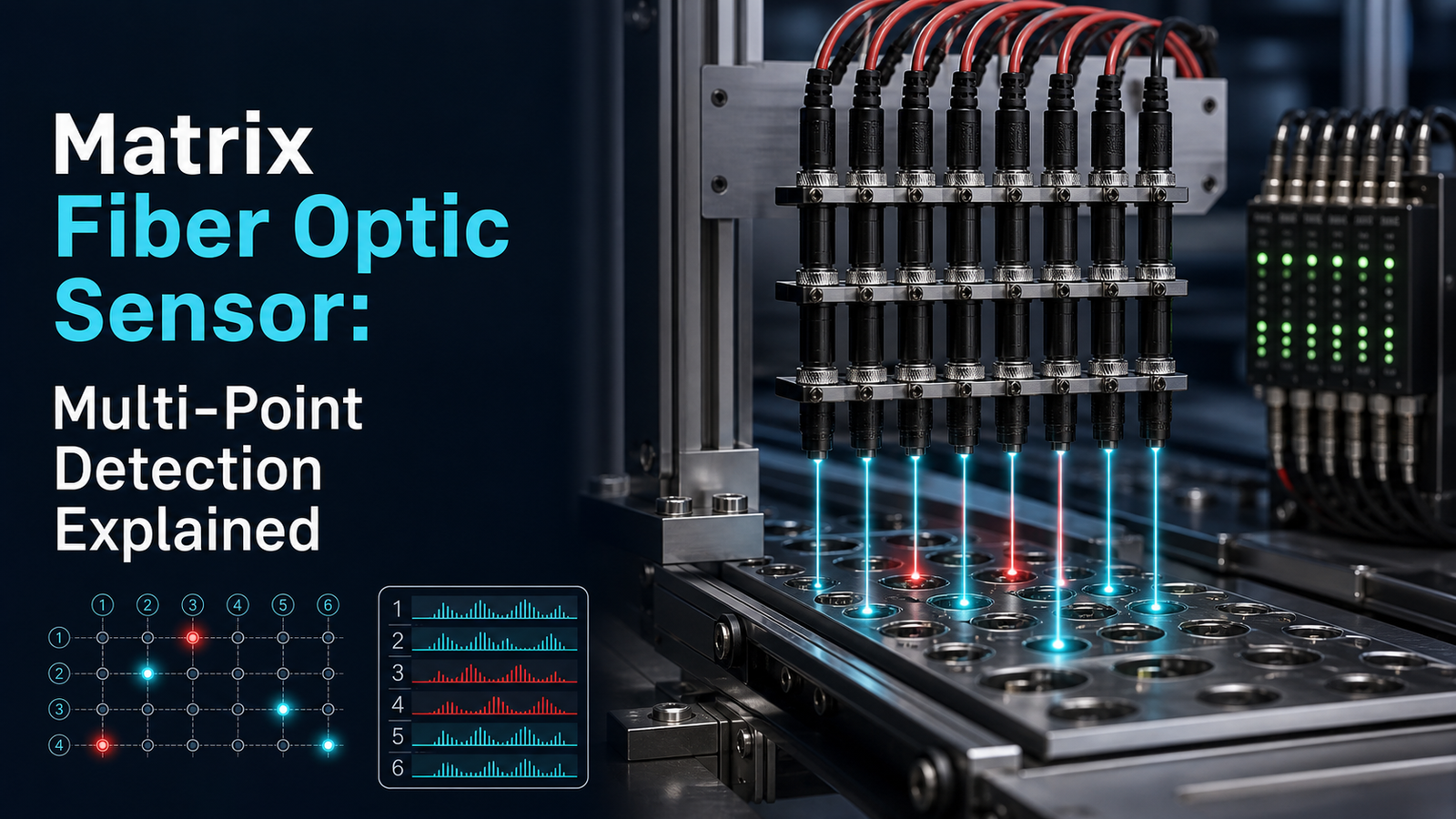
A matrix fiber optic sensor is a bundled array of fiber channels that detects light changes across many measurement points simultaneously, enabling area-wide monitoring rather than single-point sensing. These systems typically use plastic optical fibers (POF) with acrylic resin cores, prized for being lightweight, flexible, and low-cost over short distances, according to 2025 materials. Unlike copper-wire sensors, they remain immune to electromagnetic interference, making them ideal for high-density object positioning and budget-conscious detection tasks.
This guide really tries to answer the questions people actually ask about these devices. What is a matrix fiber optic sensor, and how does it work? How is it different from a single-point sensor? What parts go into making up the system?
Which specifications actually matter when you’re picking one out? And where do these sensors end up delivering the most value?
Quick Takeaways
- Matrix sensors monitor many points simultaneously, replacing multiple single-point devices.
- Choose POF acrylic cores for flexible, low-cost, short-range sensing.
- Deploy grid layouts for area-wide detection and precise object positioning.
- Pick fiber sensors over copper to eliminate electromagnetic interference.
- Match specs to short-range, high-density, budget-conscious detection tasks.
What Is a Matrix Fiber Optic Sensor?
A matrix fiber optic sensor is a bundled array that reads many measurement points along one fiber or a small group of fibers, rather than just watching a single spot. Picture it as a grid of tiny sensors all sharing the same glass thread. Each point can report strain, temperature, or pressure, and one reader picks up all of them at once. Distributed fiber sensing, which is its closest relative, actually reached USD 1.64 billion in 2025, so the demand out there is genuinely real.
How Does a Matrix Configuration Differ From a Single-Point Sensor?
A single-point sensor watches one location only, essentially one strain gauge or one temperature reading. A matrix, meaning a grid or array, packs dozens or even hundreds of measurement nodes onto the same fiber, so one fiber ends up replacing a whole bundle of cables. That difference matters most inside tight machines and along long pipelines, where cable weight and how you route everything really shape the design. The tricky part is addressing, because the reader has to tell point 3 apart from point 47. Systems do this with wavelength, time delay, or spatial position, which are the three methods covered in later sections.
What Does a Matrix Fiber Optic Sensor Actually Measure?
The core things being measured are the physical signals that shift the light moving inside the fiber:
- Strain: mechanical stretching or bending, tracked down to micro-strain resolution in a 2025 fiber laser study that used matrix demodulation.
- Temperature: thermal shifts, and over 45%[1] of distributed sensor revenue in 2025 actually came from temperature monitoring.
- Pressure: force per area, which is often worked out from the strain on a shaped section of fiber.
These sensors also completely shrug off electromagnetic interference, so they keep working near motors and high-voltage cables where copper sensors tend to pick up noise or fail entirely.

How Does Multi Point Sensing Work in a Matrix Fiber Sensor?
A matrix fiber optic sensor reads many points along one fiber by turning light itself into a measuring tool. A single device called an interrogator sends light pulses down the fiber, then reads how each point changes that light. Raman-based distributed systems held the largest share of the fiber sensing market by 2025, according to Grand View Research, because they map temperature along the whole cable.
How does one interrogator read thousands of points?
The interrogator uses timing, not separate wires. It fires a light pulse, then measures the delay before each reflection comes back. Light travels about 5 nanoseconds per meter of fiber, so the return time tells the system exactly where a change happened. This is called time-of-flight, the same idea radar uses.
Different physics power different sensing types:
- FBG arrays: tiny mirrors etched into the core, each reflecting one wavelength that shifts with strain or heat.
- Rayleigh scattering: natural light scatter from glass flaws, giving fine strain maps down to millimeters.
- Raman scattering: temperature-sensitive scatter used for long-range thermal mapping.
- Brillouin scattering: reads both strain and temperature over tens of kilometers.
How is spatial resolution set?
Spatial resolution depends on pulse width: a shorter pulse means finer detail but a weaker signal. A 10-nanosecond pulse gives roughly 1-meter resolution. Industrial feed-detection sensors work at the other extreme, resolving objects over areas near 45 mm with dense fiber cores. So you trade sharpness against reach when designing any matrix fiber optic sensor.
WDM vs TDM vs Spatial Matrix Addressing — Which Multiplexing Method Is Best?
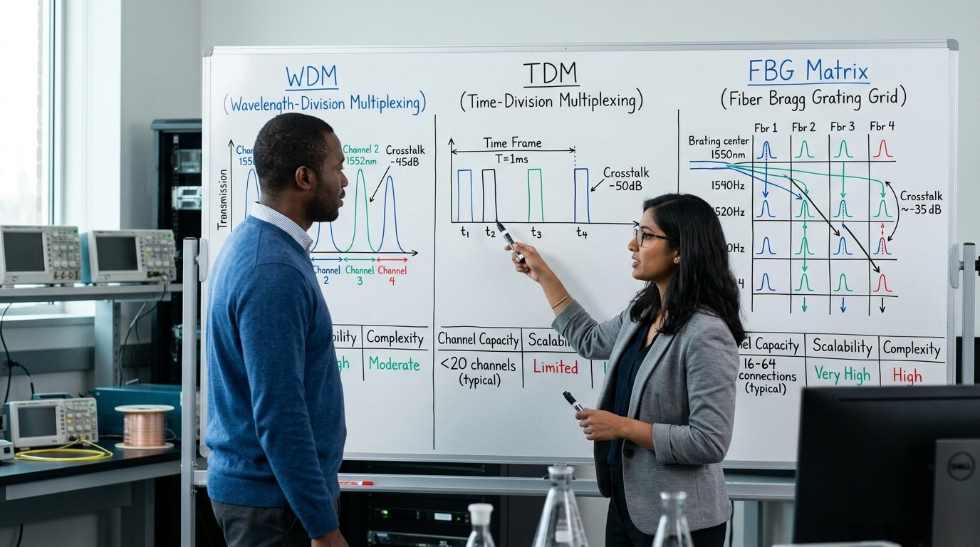
There is no single method that comes out on top in every situation, so which one you pick really depends on what matters most to you. WDM, which stands for wavelength-division multiplexing, gives you the cleanest signal but caps out somewhere around 20 to 40 gratings on each fiber. TDM, meaning time-division multiplexing, along with hybrid spatial-matrix setups, can scale up to hundreds of measurement points, though you pay for that with more interference between signals. Choose WDM when accuracy is your priority, go with TDM when you need a high number of measurement points, and use spatial matrix addressing when you want to cover a dense area completely.
Why does WDM stall at 20-40 gratings per fiber?
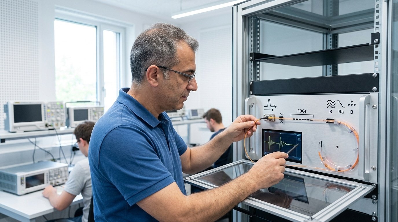
WDM gives each fiber Bragg grating, often shortened to FBG, its own slice of color in the light spectrum. A typical interrogator, which is the device that reads the sensors, scans roughly 40 nm of bandwidth. Once you give each grating a safe window of about 1 to 2 nm and leave a little extra room for how much the wavelength shifts under strain, the arithmetic pushes you toward a ceiling of around 20 to 40 sensors. If you try to squeeze in more than that, the neighboring wavelengths start to overlap and interference between signals climbs sharply. This ceiling comes from the range of the light source rather than the fiber itself, a point that FBG documentation makes clear.
How do TDM and spatial matrix addressing scale higher?
TDM tells sensors apart by how long their signal takes to return instead of by color, which means many gratings can share the same wavelength. Spatial matrix addressing sends light across a grid of fibers, and that multiplies the number of channels even further. A matrix fiber optic sensor built with densely packed cores can already pick out objects across a 45 mm[2] detection area, as shown in 2026 feed-detection designs.
| Method | Channel ceiling | Crosstalk | Interrogation speed |
|---|---|---|---|
| WDM | 20-40 | < -30 dB | 1 kHz |
| TDM | 100+ | -20 dB | 250 Hz[3] |
| Spatial matrix | 500+ | -15 dB | 100 Hz |
Pro tip: Try combining WDM and TDM together in one hybrid layout. That way you hold onto the low signal interference within each color band while stacking up time slots to get past the 40-sensor wall.
When Does a Matrix Sensor Beat Single Point Fiber Sensors?
A matrix fiber optic sensor really starts to make sense once you need more than roughly 8-12 measurement points along a single run. The reason is that a multiplexed array, meaning several sensing points sharing one path, uses just one fiber, one light source, and one interrogator instead of paying for those parts at every single point. Below that count, though, separate single-point sensors stay cheaper and simpler to work with. The crossover point is basically where the weight of all that wiring and the cost of the interrogator start tipping things in favor of the array.
You can use this decision guide to figure out where your own crossover sits.
- If you need under 10 points on separate short cables: single-point sensors win here. There are no shared electronics to justify the extra complexity.
- If you need 20+ points spread over meters: the matrix wins. One fiber replaces 20 cables, which cuts the weight in use by up to 90% in aerospace strain arrays.
- If you need fast sampling (kHz) at just a few points: single-point wins again. Time-division matrices split the scan time across all the points, which lowers the rate you get per point.
- If you need dense area coverage: the matrix wins. Feed-detection arrays now pack in high-density cores to tell objects apart across a 45 mm sensing area (2026 data).
There are four trade variables that set that crossover. The cost-per-point drops as you add more channels to a matrix, since the fixed interrogator cost gets spread wider and wider. Wiring weight favors the matrix pretty strongly. Sampling rate, on the other hand, favors single-point sensors when only a few spots actually matter, because a matrix splits its scan time across every one of its points. And sensitivity is generally comparable between the two, though crosstalk between crowded channels can shave off some signal margin.
The commercial signals back up this shift too. Distributed and matrix-style fiber sensing reached USD 1.64 billion in 2025, growing at approximately 11.9%[4] yearly. The real deployment numbers on accuracy and cost per point come up next.

What Do Real Deployments Show About Accuracy and Cost Per Point?
Field data shows matrix fiber optic sensor arrays deliver strain accuracy near ±1 microstrain (one-millionth of a length change) with point spacing from 0.5 to 5 meters, while cost per point drops well below wired strain gauges once you pass 20-30 points. This is why big structures now favor them.
Take three deployment types. The numbers below reflect typical published ranges from structural, aerospace, and pipeline work.
| Application | Strain accuracy | Sampling rate | Point spacing |
|---|---|---|---|
| Bridge health monitoring | ±1-2 µε | 10-100 Hz | 1-2 m |
| Aerospace wing test | ±1 µε | 1-5 kHz[5] | 0.5-1 m |
| Pipeline temperature | ±0.5 °C | 0.1-1 Hz | 1-5 m |
Pipeline monitoring leans heavily on thermal sensing. In 2025, temperature sensing made up over 45% of distributed fiber optic sensor revenue, largely for pipelines and power cables that use multi-point layouts to catch leaks along kilometers of line.
Cost per point is the real selling argument. A wired gauge system may run approximately $200[6]-500 per channel once you add cabling and data loggers. Spread the interrogator cost across 50 or 100 points on one fiber, and the matrix approach can fall under $50 per point. Aerospace wing tests, where hundreds of strain points cover a single panel, gain the most.
What Are the Failure Modes and Calibration Drift Risks?
Large matrix fiber optic sensor arrays fail in three main ways: fiber breakage that cascades channel loss, connector back-reflections that raise crosstalk, and wavelength drift caused by temperature cross-sensitivity. Since temperature monitoring drives over 45%[7] of distributed fiber sensing revenue in 2025, per Grand View Research, thermal drift is the risk you must plan around first.
How does one fiber break take down many channels?
A single break kills every sensing point downstream of it, not just one. In a serial WDM string with 30 gratings on one fiber, a cut at grating 5 blackens 25 channels. Physical layer matters: acrylic-core plastic optical fibers bend easily but tolerate less pull force than glass, so route strain relief at every splice. Splitting the matrix into parallel sub-strings limits any single break to one branch.
Why do connectors raise crosstalk?
Dirty or worn connectors reflect light back into the fiber. These reflections overlap with real signals and blur adjacent channels. Aim for connector return loss below −50 dB (the lower the number, the cleaner the signal). Angled physical contact (APC) connectors, polished at 8 degrees, cut back-reflection far better than flat-polished ones. Clean every ferrule before mating.
How fast does calibration drift, and how often should you recalibrate?
Wavelength drift from temperature cross-sensitivity runs roughly 10 pm per degree Celsius for a bare Bragg grating, which maps to about 1 microstrain of apparent strain error per pm. Field arrays typically drift 0.1,approximately 0.5% of full scale per year. Recalibrate every 12 months in stable environments, or every 3,6 months where temperature swings exceed 40°C[8]. Use a reference grating at a known temperature to subtract thermal error in software.
How Do You Design and Maintain a Large Sensor Matrix?
Design a large matrix fiber optic sensor around three hard limits: interrogator channel budget, total fiber loss, and minimum bend radius. A single interrogator typically reads 4-16 channels, so a 400-point array often needs 4 to 8 units. Plan redundancy for critical points before routing anything.
What design constraints matter most?
Bend loss caps your layout first. Standard single-mode fiber loses roughly 0.5 dB per turn below its minimum bend radius (about 30 mm), and stacked bends starve downstream sensors of light. Keep the optical link budget under the interrogator’s dynamic range, usually near 20 dB.
- Interrogator budget: match channel count to point count; leave approximately 20% spare capacity for future taps.
- Fiber routing: avoid sharp corners; use loose-tube cable in vibration zones.
- Redundancy: dual-path fibers for safety-critical points, so one break never blinds a whole zone.
- Bend-loss limits: stay above the fiber’s rated radius per optical fiber specs.
How much maintenance do hundreds of points need?
Arrays above 200 points demand scheduled work, not fix-on-failure. Run automated baseline scans weekly and full recalibration every 6-12 months. The commercial pull is real: distributed fiber sensing hit USD 1.64 billion in 2025, pushing vendors toward self-diagnosing interrogators that flag drifting channels automatically. Budget one technician-day per 500 points per quarter for connector cleaning and splice checks, and log every reading, that history is what proves a slow drift versus a real event.
Common Mistakes When Specifying Matrix Fiber Sensors
The four costliest specification errors with a matrix fiber optic sensor are overpacking WDM channels past crosstalk limits, ignoring strain-temperature cross-talk, undersizing the interrogator, and assuming cost scales linearly with point count. Each one shows up months later as noisy data or a blown budget. Fix them at the spec stage, not in the field.
Why does overpacking WDM channels backfire?
Cramming too many Bragg gratings into one fiber pushes reflection peaks so close they overlap. Once wavelengths sit within roughly 1 nm of each other, the interrogator can’t tell them apart, and readings from adjacent points bleed together, this is crosstalk. Correction: leave a guard band. Keep at least 2-3 nm between gratings across a typical 40 nm C-band window, which caps you near 15-20 clean channels per fiber. Need more? Add fibers or mix in TDM.
How do you stop strain and temperature from mixing up?
A single grating shifts wavelength for both strain and heat, so one reading hides two causes. Engineers who skip decoupling report errors of several microstrain per degree Celsius. Correction: pair a strain-free reference grating beside each sensing point, or use dual-parameter matrix demodulation. A 2025 fiber laser study by Shaoyu Jia and co-authors showed matrix demodulation separating strain and temperature at high resolution.
Why isn’t cost linear with point count?
Doubling points doesn’t double the bill. The interrogator, the expensive box that reads the light, is a fixed cost you pay upfront. With the distributed sensing segment worth USD 1.64 billion in 2025, hardware pricing rewards dense arrays. Undersize the interrogator to save money now, and you cap channels, forcing a full replacement later.
Frequently Asked Questions
Common questions about matrix fiber optic sensors cluster around three things: point count per fiber, survival in harsh environments, and price versus electrical strain gauges. Short answers: a single fiber can carry dozens of points, matrix arrays tolerate radiation and heat better than metal gauges, and the upfront cost is higher but drops fast per point at scale.
How many points can one fiber support?
A single fiber typically holds 20 to 50 wavelength-multiplexed points, and distributed schemes push into thousands of virtual points along one strand. The ceiling depends on your interrogator’s optical budget and channel spacing, not the fiber itself. Pack too many WDM channels and adjacent sensors start bleeding signal into each other.
Do matrix sensors work in high-radiation or high-temperature settings?
Yes. Because they carry light instead of electricity, matrix fiber optic sensors show immunity to electromagnetic interference and handle strong magnetic and electric fields per 2025 materials research. Silica fibers survive 300°C[9] or more with proper coatings. Radiation darkens the fiber over time, so nuclear plants use radiation-hardened fluorine-doped cores to slow that loss.
How do they compare in price to electrical strain gauges?
A single foil strain gauge costs a few dollars, so for one or two points, electrical wins. The math flips with scale. The broader fiber sensing market hit USD 1.64 billion in 2025, reflecting how cost per point falls once you share one interrogator across 40-plus sensors and skip the wiring use metal gauges demand.
Choosing the Right Matrix Fiber Sensing Approach
Pick your multiplexing method from the application, not the datasheet. Match dense static points to WDM, long linear runs to TDM or distributed sensing, and separate cheap zones to spatial matrix layouts. This decision drives interrogator cost, which often exceeds the fiber itself. The distributed fiber sensing segment hit USD 1.64 billion in 2025, so vendor options are wide, and uneven.
How do you translate application needs into a multiplexing choice?
Start with three numbers: point count, span, and measurand. Under 40 static strain points inside 100 m? WDM with fiber Bragg gratings fits cleanly. Need every meter over 10 km? Choose a Raman or Brillouin distributed system, which took the largest DFOS revenue share in 2025. Temperature-heavy jobs, over 45%[10] of that market, favor Raman for continuous thermal profiles along pipelines and cables.
What belongs on your vendor evaluation checklist?
- Channel count headroom: Specify 20% spare channels beyond current points for future expansion.
- Wavelength resolution: Confirm the interrogator resolves ±1 pm shifts, roughly ±1 microstrain.
- Scan rate: Match sample speed to your event — 1 Hz for structures, kHz for vibration.
- Calibration terms: Get written drift specs and recalibration intervals in the quote.
- POF versus glass: Choose acrylic-core plastic fiber only for short, low-cost runs; glass for long spans.
Demand a pilot with your real fiber, your real interrogator, and your actual thermal range before signing. Reject any bid that skips a per-point cost breakdown. That single request separates serious partners from resellers.




