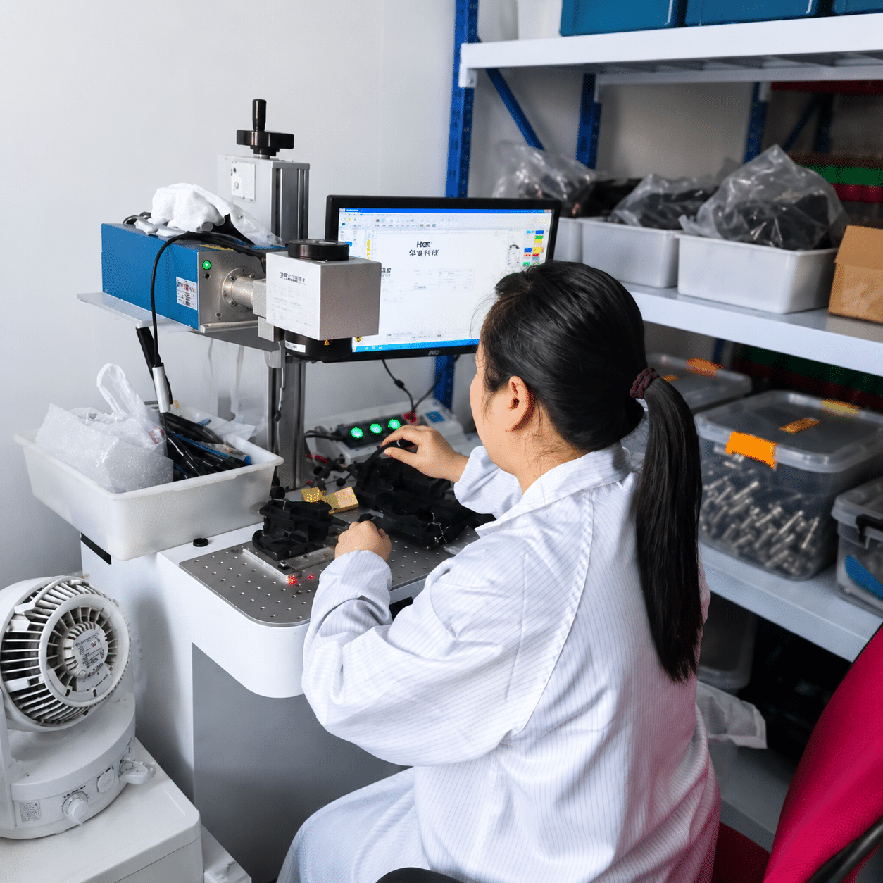
Matrix Fiber Optic Sensors for Multi-Point Detection.
XSZ matrix fiber optic sensors help detect multiple positions, arranged parts, wide object areas and small target groups where one single-point fiber head is not enough.
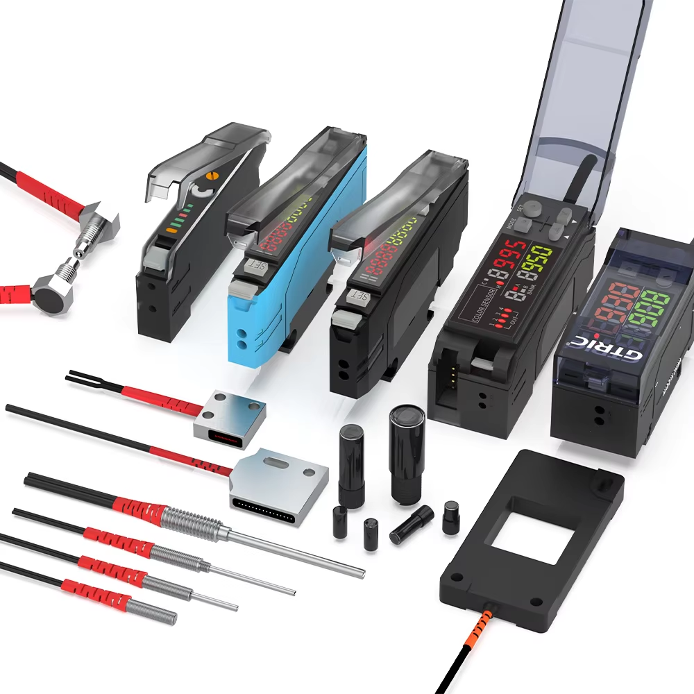
- Multi-point optical sensing
- Small part presence checks
- Fixture and array detection
- Factory model selection support
When one sensing point cannot cover the real production layout
Matrix fiber optic sensors are useful when the machine must check several positions at once or confirm whether a target crosses a defined optical area.
Multi-position checks
Use one sensing concept to monitor several aligned targets, product rows, holes, slots or fixture positions.
Defined detection area
Improve coverage when the target position has tolerance, movement variation or multiple possible passing locations.
Small target reliability
Fiber optic sensing helps detect small parts, thin edges and arranged components in compact automation equipment.
Designed for arranged parts, rows and repeatable machine checks
Use matrix fiber optic sensors when the detection task depends on area coverage, point spacing and repeatable target position.
Choose by detection layout, not only by sensing distance
The right matrix fiber optic sensor depends on how many positions must be detected, the spacing between targets and how the output should be used by the machine controller.
| Selection Point | What to Confirm | Why It Matters | XSZ Support |
|---|---|---|---|
| Detection width | Total area or row length to monitor | Prevents missed targets outside the sensing zone | Recommend layout and sensing head arrangement |
| Point spacing | Distance between parts, holes or fixture positions | Prevents two targets from being read as one unstable signal | Check spacing against target size and tolerance |
| Target size | Smallest object, edge or gap to be detected | Defines required optical resolution and sensitivity | Match fiber head type and amplifier setting |
| Mounting space | Available bracket, angle and cable route | Improper mounting causes alignment drift and false triggering | Support compact mounting and cable options |
| Output logic | NPN, PNP, NO, NC and controller input | Ensures the sensor signal works with the PLC or control board | Help confirm wiring and amplifier output |
Matrix fiber optic sensor or single-point fiber sensor?
Both can be useful. The better choice depends on whether your problem is one precise detection point or a wider multi-position detection task.
Multiple points or wider coverage
Choose matrix detection when targets may appear across a row, tray, fixture or defined area and one point cannot cover the real process.
One fixed target position
Choose a normal fiber head when only one small object, edge or gap must be detected at a stable location.
Enough space for sensor body
Choose a standard photoelectric sensor when the installation space is larger and the detection target is less complex.
Common causes of unstable matrix fiber optic detection
Most problems come from choosing the sensor before confirming the real target path, spacing tolerance and machine signal requirement.
Coverage too narrow
If the monitored area does not cover product movement tolerance, some targets may pass outside the stable sensing zone.
Spacing not reviewed
Very close targets, uneven gaps or tilted parts may require a different sensing arrangement or amplifier adjustment.
Wrong output setup
The sensor must match the PLC input, response time, output mode and machine cycle to avoid missed or delayed signals.
Configure the sensor around your machine layout
For matrix detection, the mechanical layout and control logic are just as important as the sensing principle.
Detection geometry
Select by detection width, point number, optical path, target spacing and allowed installation angle.
Fiber and cable route
Confirm head shape, cable length, bend radius, moving cable path and protection from pulling or abrasion.
Amplifier and output
Match sensitivity, response time, display, teach setting, NPN/PNP output and NO/NC logic to the controller.
Send these details for faster model recommendation
Matrix fiber optic sensors often need application matching. Sharing the target and layout information helps reduce trial-and-error during installation.
- Target material, color, surface condition and smallest size.
- Number of detection points or total area that must be covered.
- Spacing between targets, holes, lanes or fixture positions.
- Mounting distance, available bracket space and cable route.
- PLC input type, voltage, response speed and output logic.
| Application Detail | Recommended Check | Risk If Ignored |
|---|---|---|
| Target tolerance | Measure left/right and height variation | Intermittent missed detection |
| Target spacing | Confirm minimum and maximum gap | Signal overlap or false trigger |
| Mounting angle | Check optical alignment and fixture stability | Weak signal after vibration |
| Machine speed | Match amplifier response time | Delayed output or missed object |
| Environment | Review dust, oil, light and cleaning method | Reduced stability over time |
Tell us the layout. We help match the sensor configuration.
For matrix fiber optic applications, XSZ can review drawings, target photos, fixture dimensions and controller requirements before recommending a model.
Share target layout
Send photos, drawings, target spacing, width and movement direction.
Confirm signal needs
Confirm output type, controller input, response time and wiring method.
Choose final setup
Select sensor, amplifier, cable and mounting direction for repeatable detection.
Manufacturer support for standard and custom matrix fiber optic projects
XSZ supports B2B buyers with model selection, cable options, labeling, packaging and repeat order supply for machine builders and automation distributors.
Compare related optical sensing options
If the application does not need matrix coverage, a standard fiber optic or photoelectric solution may be easier to install.