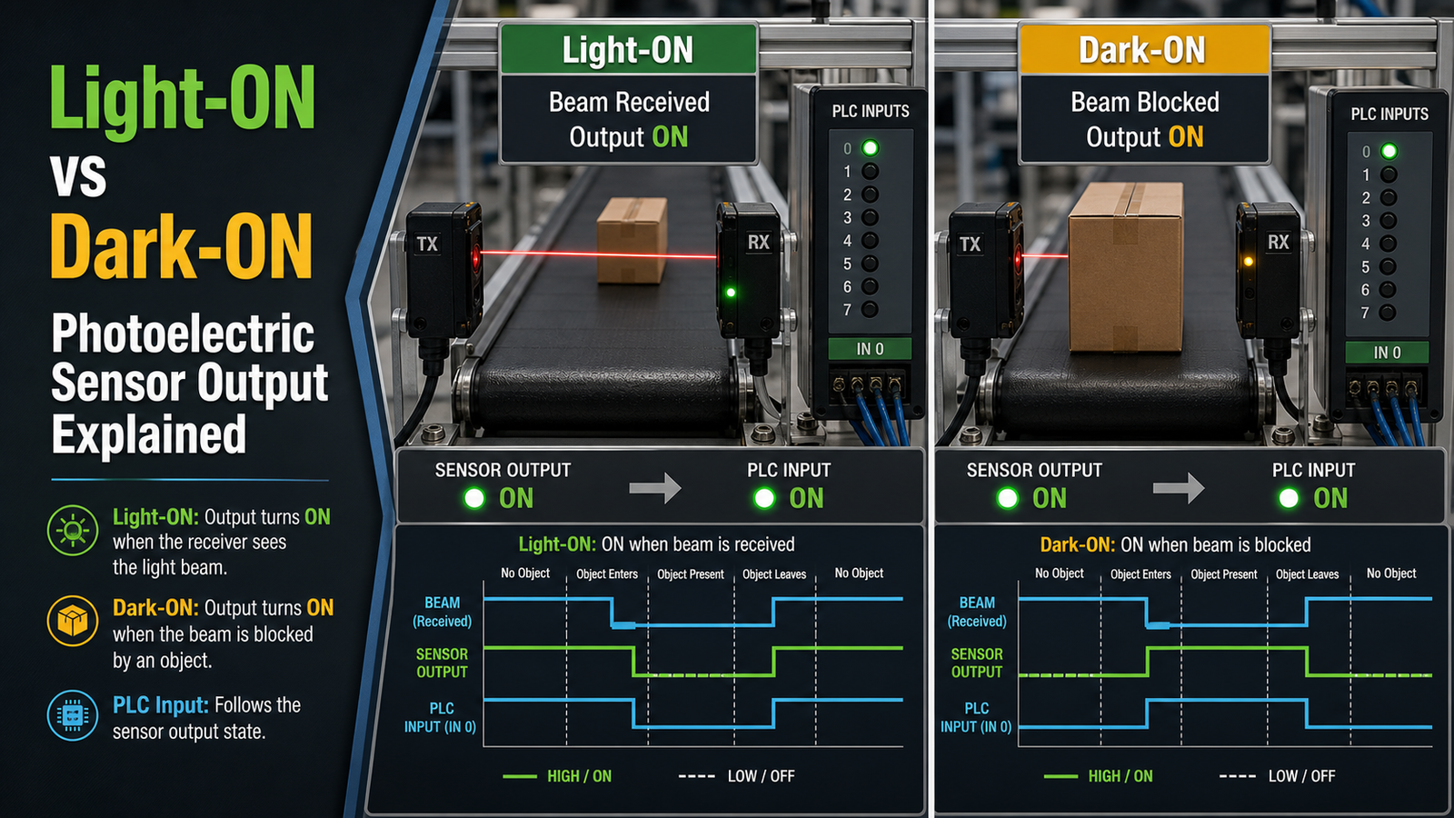
A light on dark on sensor lets you choose whether a photoelectric sensor’s output activates when the receiver detects light (light-on) or when the beam is blocked (dark-on). Per AutomationDirect’s 2024 documentation, a light-operate sensor is “actively true when it detects light,” while dark-operate turns true when it sees no light. As of 2026, many industrial sensors ship with programmable modes switchable via a wire, DIP switch, or button, and through-beam setups often default to dark-on for object presence detection.
How does the wiring actually change when you switch between the two? When is it better to pick one mode over the other? Which sensing modes end up affecting the logic? And how do you keep false triggers from happening on the line?
Quick Takeaways
- Light-ON activates output when the receiver detects light directly.
- Dark-ON activates output when an object blocks the light beam.
- Choose dark-on for through-beam object presence detection setups.
- Diffuse and retroreflective modes reverse which condition detects objects.
- Switch modes using programmable wires, DIP switches, or push buttons.
What do light-on and dark-on mean in a photoelectric sensor?
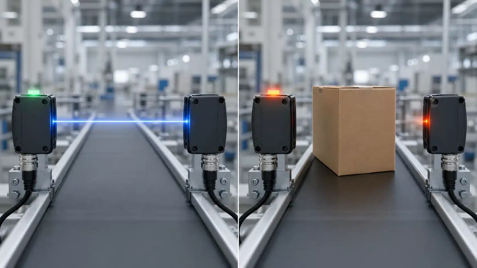
Light-on means the sensor output becomes active when the receiver picks up light. Dark-on means the output becomes active when that light gets blocked. According to AutomationDirect’s 2024 documentation, a light-operate sensor is “actively true when it detects light,” while a dark-operate sensor turns true when it sees no light at all. These terms are describing how the output behaves based on the light received, not whether some object is actually sitting there.
That difference trips up a lot of technicians, and it makes sense why. A dark-on sensor firing does Not automatically mean “object detected.” In a through-beam setup, dark-on fires when the beam gets blocked, and that blockage Is the object. But in a diffuse setup, an object Reflects light back toward the sensor, so detecting it actually creates a Light condition instead. It is the same “object present” event, though the sensor logic is completely opposite, so you always want to match the mode to the beam type rather than to your gut feeling about the part passing by.
On the real hardware, you will see the selector marked L.On and D.On, or sometimes LO (Light Operate) and DO (Dark Operate). As of 2026, many industrial photoelectric sensors come with programmable light-on/dark-on modes, so a single part number ends up covering both wiring approaches. Commercial M18 units, for instance, pair this switchable logic with PNP or NPN digital outputs, which lets you match the same light on dark on sensor to almost any PLC input without swapping out the physical device. Functionally, it works like a polarity switch for the output.
The optics stay exactly the same, and only the “true” condition gets flipped around.
How does the output signal change between light-on and dark-on modes?
The two modes flip the output opposite to each other for the same beam condition. A light-on sensor’s output is active (true) when the receiver sees light, and off when light is blocked. A dark-on sensor does the exact reverse. Per AutomationDirect’s 2024 sensor documentation, a dark-operate output is actively true when the beam is blocked or misaligned. Trace it by watching one thing only: the light hitting the receiver. Everything else follows from that single input.
| Receiver light status | Light-on output | Dark-on output |
|---|---|---|
| Light received | ON (active) | OFF |
| Light blocked | OFF | ON (active) |
Notice the signals are always inverted. If light-on reads ON, dark-on reads OFF for that same instant. This matters on the wiring bench: a phototransistor-based receiver leaks a small Dark current (a tiny flow even with no light), and a 2025 sensor buyer’s guide warns this dark current climbs with temperature. That can nudge a marginal threshold and cause a false ON in dark-on mode on a hot line.
Practical tip for any light on dark on sensor: after setting the mode, force both states by hand. Wave your hand through the beam and confirm the output toggles the way the table predicts. If it doesn’t invert cleanly, your switching threshold is set too close to the dark current floor.
How do the two modes behave with through-beam, retroreflective, and diffuse sensors?
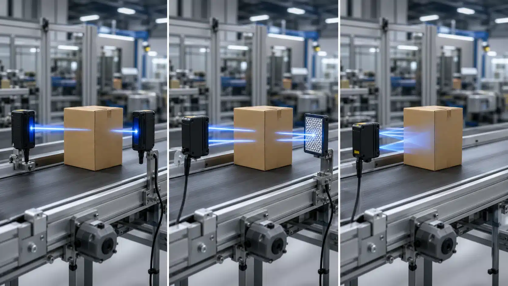
The same light-on dark-on sensor setting triggers on opposite physical events depending on sensing style: in through-beam and retroreflective sensors, a target Blocks the beam, but in diffuse mode the target Reflects light back to the receiver. So “no light at the receiver” means “object present” in the first two, and “object absent” in diffuse mode.
Picture a box on a conveyor. In a through-beam pair (separate emitter and receiver), the box interrupts the beam, the receiver goes dark. In diffuse mode (emitter and receiver in one housing), that same box sends light bouncing straight back, the receiver goes bright. AutomationDirect’s 2024 documentation makes the split explicit: for through-beam and retroreflective sensors, a dark-operate output is true when the beam is blocked or misaligned. For diffuse sensors, a dark-operate output is true when No object is present, and goes false the moment an object reflects light back.
- Through-beam: object breaks beam → receiver dark → dark-on output true.
- Retroreflective: object breaks beam to reflector → receiver dark → dark-on output true.
- Diffuse: object reflects beam back → receiver bright → light-on output true.
Practical tip: for object-present detection, choose light-on for diffuse but dark-on for through-beam and retroreflective. Set the mode by asking “does my target block or reflect?”, not by copying the last machine’s config.
How do you switch a photoelectric sensor between light-on and dark-on modes?
You can switch between modes in one of three ways: flip a DIP switch (which is a small physical toggle, sometimes shown as an L/D wire), run through a teach-in button sequence, or change an IO-Link parameter. Most modern units are programmable these days. As of 2026, a lot of industrial photoelectric sensors ship with selectable light-on/dark-on logic, so you generally don’t need to rewire anything. Pick whichever method your particular model supports, and then verify it before you run actual production.
What are the three physical and digital switching methods?
The method you use really depends on your sensor’s hardware. You just need to match yours to the table below.
| Method | Action | Typical model type |
|---|---|---|
| DIP switch | Slide L/D toggle to L or D position | Compact block sensors |
| L/D wire | Tie select wire to +V (light) or 0V[1] (dark) | Multi-wire cylindrical |
| Teach-in button | Hold MODE 2-3 seconds until LED blinks | Programmable M18 units |
| IO-Link | Write “Output Logic” parameter via master | Smart factory sensors |
How do you verify the mode took effect?
You’ll want to confirm the switch actually worked before you trust it out on the line. Block the beam by hand, and then check whether the output LED matches what you intended. On a Light-on dark-on sensor, the output LED should light up when the beam hits the receiver in light-on mode, and it should go dark when the beam is blocked.
Then run a second check right at the PLC. Watch the input bit toggle as you interrupt the beam three times in a row. If it stays stuck in one state, you probably set the wrong logic or crossed a wire somewhere. It’s best to fix it right now, because a mode error caught here only costs you a few seconds, rather than a whole scrapped batch of parts.
How does mode selection connect to NPN, PNP, and PLC input logic?
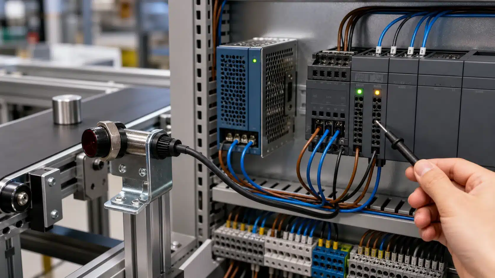
Mode and output type combine to set the exact voltage your PLC reads. Light-on/dark-on decides When the output fires; NPN or PNP decides How it fires. A dark-on PNP sensor sends 24V[2] to the input when the beam is blocked, while the same dark-on sensor in NPN pulls that input to 0V[3] instead. AutomationDirect’s 2024 notes confirm a dark-operate output is actively true when no light reaches the receiver.
What’s the difference between NPN sinking and PNP sourcing here?
NPN sinks current, pulling the PLC input toward 0V (ground) when active. PNP sources current, pushing 24V[4] to the input when active. Commercial M18 photoelectric sensors as of 2026 typically offer both PNP/NPN digital outputs with programmable LO/DO logic. So one part number gives four behaviors: light-on PNP, light-on NPN, dark-on PNP, dark-on NPN.
How does the PLC input read high or low in each case?
| Mode + Output | Object present | PLC input state |
|---|---|---|
| Light-on, PNP | Beam clear | HIGH (24V[5]) |
| Light-on, NPN | Beam clear | LOW (0V) |
| Dark-on, PNP | Beam blocked | HIGH (24V[6]) |
| Dark-on, NPN | Beam blocked | LOW (0V[7]) |
Your ladder logic must match this pairing. Pick dark-on PNP for “object detected = input ON,” and write a normally open contact. Choose NPN, and you often invert the rung. Set the wrong combo and a Start command triggers on empty conveyor. Always verify the DIP setting against the wiring diagram before initial startup.
Light-on vs dark-on — which mode should you choose?
Choose the mode that makes your output active during the state you care about detecting. The two modes are mirror images, so the choice comes down to which event you must catch: pick dark-on when a fault, missing part, or blocked beam is that event, and pick light-on when a present part reflecting light is the trigger. As of 2024, AutomationDirect defines a dark-operate sensor as one whose output is true when no light reaches the receiver. Three factors drive the call: target-vs-background contrast, fail-safe need, and whether your PLC input wants normally-open or normally-closed logic.
| Scenario | Sensor type | Recommended mode | Why |
|---|---|---|---|
| Dark part on bright conveyor | Diffuse | Dark-on | Low reflection reads as dark = output true |
| Part-present confirm | Diffuse | Light-on | Reflected light = part detected |
| Broken-web / jam detect | Through-beam | Dark-on | Blocked beam signals fault (fail-safe) |
| Clear-object counting | Retroreflective | Light-on | Beam returns when path is clear |
Fail-safe logic tips the scale. A broken wire, dead LED, or misaligned emitter all mimic a dark condition. So a dark-on light on dark on sensor treats any failure as “trigger true,” alerting the line instead of silently missing parts. That’s why safety-adjacent detection favors dark-on.
Follow the tree: Is the alarm state “light blocked”? Go dark-on. Is the event “part reflects light”? Go light-on. Then match output type to your input card.
Why does the wrong mode cause misdetection, and how do you troubleshoot it?
The wrong mode inverts your output logic, so the sensor reports the opposite of reality. A dark-on setting on an empty conveyor stays “true” because nothing reflects light back, your PLC reads a part when none exists. Fix it by matching mode to the state you actually want to detect, then confirming output type and sensitivity separately.
Three symptoms point straight to a mode mismatch. First, Inverted output: the beam is clear but the load stays energized. That’s a light-on/dark-on sensor set backward for your target. Second, Triggering on an empty conveyor: classic dark-operate behavior, since AutomationDirect’s 2024 diffuse-mode notes confirm a dark-operate output is true when no object reflects light back. Third, Missing low-contrast targets: usually not mode at all, it’s sensitivity margin.
Run this diagnostic checklist in order:
- Confirm mode first: block the beam by hand. Output should flip. If it flips the wrong way, swap light-on/dark-on.
- Check output type: measure voltage at the signal wire. NPN sinks to 0 V[8] active; PNP sources to 24 V active. A mismatch here mimics a mode fault but is a wiring/logic problem.
- Test sensitivity last: if the target is dark or matte, dark current rises with temperature and erodes margin. A 2025 ambient-light sensor guide notes phototransistor dark current increases with heat, shrinking your detection window.
Isolate one variable at a time. Never adjust mode and sensitivity together, you’ll chase a phantom fault for an hour.
Common mistakes engineers make with light-on and dark-on settings
The biggest mistake is assuming dark-on always means “target present.” That’s only true for through-beam and retroreflective sensors, where an object blocks the beam. Per AutomationDirect’s 2024 application notes, a diffuse-mode dark-on sensor turns its output true when No object reflects light back, the exact opposite meaning. Getting this backward flips half your logic.
Here are the errors that bite engineers most often:
- “Dark-on = object detected” everywhere: True for beam-break sensing. False for diffuse. A diffuse light-on dark-on sensor detects the target when light Returns, so light-on means “part present.”
- Confusing mode with fail-safe wiring: Mode sets output polarity. Fail-safe is a design choice about which state means “safe.” Pick the mode so a blocked or dead beam drives the alarm state — don’t assume the default does this.
- Ignoring dark current at high temperature: A 2025 ambient-light sensor buyer’s guide warns that phototransistor dark current rises with heat. On M18 sensors rated to 140 °F[9], a marginal threshold that works cold can false-trigger warm. Set margins with 15–approximately 20%[10] headroom.
- Mixing up mode and output type: Dark-on describes when the output activates. PNP/NPN describes how it drives voltage. Both must match your PLC input.
The correct mental model: mode answers “active on light or dark?”, sensing style answers “what does dark physically mean here?” Solve them separately, then combine.
Frequently asked questions about light-on and dark-on sensor outputs
Light-on doesn’t automatically equal normally open, dark-on is usually the fail-safe choice for stops, and you can confirm the active mode with a multimeter in under a minute. Below are the three questions engineers search for most, answered with the specifics you need on the wiring bench.
Does light-on mean normally open (NO)?
No, not always. Light-on describes When the output goes active; NO/NC describes the switch’s resting state. On a PNP light-on sensor, the output is off (open) when the beam is blocked and switches to +24 V when light hits the receiver. That behaves like NO. But pair light-on with an NC contact and the logic inverts. Read the datasheet’s truth table, not the name.
Which mode is safer for a fail-safe stop?
Dark-on. In a fail-safe guard, you want the machine to stop if the beam breaks Or the sensor loses power. A dark-operate output is true when the beam is blocked or misaligned, matching a real fault. Per AutomationDirect’s 2024 guidance, dark-operate outputs are actively true when the light beam is blocked. Wire that into a normally-energized safety relay so a dead sensor also triggers the stop.
How do you test the mode with a multimeter?
Set your meter to DC volts. Probe the signal wire against the sensor common. Block the beam, then clear it, and watch the reading flip between 0 V and roughly 24 V (or supply voltage). If voltage appears when light is present, you’ve a light-on light on dark on sensor. Note that phototransistor outputs carry a small dark current that rises with temperature, so expect a few millivolts, not a true zero.
Choosing and configuring the right mode with confidence
Verify three things together before initial startup: the mode (light-on or dark-on), the output type (PNP or NPN), and the PLC input logic. Get one wrong and your program reads the opposite of reality. Since many 2026 industrial sensors ship with programmable light-on/dark-on modes, the setting is a decision you own, not a fixed part number.
Run this quick check at the panel, in order:
- Mode: Pick the mode that makes the output active during the state you must catch. Favor dark-on when a blocked beam or missing part is the alarm event. Favor light-on when a clear path or present target is the “go” signal.
- Output type: Match PNP (sourcing) or NPN (sinking) to your PLC input card. A PNP output feeds a sinking input; NPN feeds a sourcing input.
- PLC logic: Force the sensor high and low by hand. Confirm the input bit matches what the program expects — active-high or active-low.
Wire logic (LO/DO) is defined the same across vendors: light-operate outputs true when light hits the receiver, dark-operate outputs true when it doesn’t, per AutomationDirect’s 2024 documentation. Write the chosen mode and output type on the terminal drawing. That one note saves the next technician a 20-minute logic hunt.
Bench-test the light on dark on sensor before it goes live. Trigger it, watch the LED, and read the actual PLC bit, never trust the label alone.




