
Industrial position sensing guide
Proximity Sensor vs Limit Switch: Which Should You Use?
Choose a proximity sensor when non-contact detection, high cycling, or minimal mechanical wear matters. Choose a limit switch when the machine can provide controlled physical travel and you need a straightforward mechanical operating point. The correct choice still depends on target, environment, output circuit, failure consequence, and the exact model ratings.
Useful for frequent cycles, delicate targets, short sensing gaps, and applications where contact wear is undesirable.
Useful for definite end-of-travel actuation when a cam, dog, lever, or plunger can move through the specified stroke.
Purchase price is only one term. Include mounting, wiring, commissioning, maintenance, production loss, and spares.
Guard interlocking requires a risk assessment, suitable safety-rated device, architecture, diagnostics, and validation.
The direct answer
Neither device is universally better. They solve the same position question in different ways.
A proximity sensor detects a nearby target without mechanical contact. An inductive model responds to metal through an electromagnetic field; capacitive and magnetic proximity technologies respond to other target properties. A limit switch changes its electrical contacts only after a machine part physically moves its actuator.
The non-contact method usually removes actuator and contact wear from the sensing event, but it introduces electronic application limits such as target material, sensing distance, surrounding metal, mutual interference, leakage current, voltage drop, and output compatibility. The mechanical method gives the machine a physical operating point, but actuator alignment, overtravel, release travel, contact loading, arcing, and contamination become part of reliability.

See the physical difference
One detects a field change. The other waits for actuator movement.
These two device families can both report position to a controller, but the evidence, installation rules, and failure modes are not interchangeable.
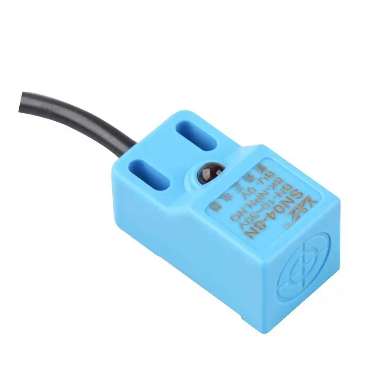
Proximity sensor
The sensing face must see the correct target inside a controlled operating gap. No actuator needs to be pressed, but the installation must preserve signal margin.
- Requires a compatible target and sensing principle
- Usually needs power and an electronic output circuit
- Can provide fast, repeatable switching without physical impact
- Must be checked for mounting metal, EMI, temperature, vibration, and contamination

Limit switch
A cam, dog, door, slide, or machine member applies force to a lever, roller, plunger, or other actuator until the internal contacts change state.
- Requires correct approach direction, force, travel, and release
- Can provide dry contacts, subject to the exact electrical ratings
- Actuator and contacts have model-specific mechanical and electrical durability
- Must be protected from impact, overtravel, sticking, cable-entry leaks, and contact arcing
Proximity sensor vs limit switch
Compare the application evidence, not generic catalog adjectives.
The following table identifies what normally changes the decision. Exact distance, current, response time, protection rating, temperature, durability, and approvals remain model-specific.
| Decision factor | Proximity sensor | Limit switch | What to verify |
|---|---|---|---|
| Detection event | A compatible target changes an electromagnetic, electric, or magnetic field without touching the sensing face. | A machine part physically moves the actuator through its operating point. | What physical event proves the required machine state? |
| Target requirement | Depends on technology. Inductive sensors require metal; capacitive and magnetic models use different target properties. | The target must provide a suitable cam surface, approach, force, travel, and release motion. | Material, size, shape, speed, position tolerance, and direction of approach. |
| Physical wear | No actuator impact or moving output contacts in common solid-state models. | Actuator, spring, seals, bearings, and electrical contacts can wear under repeated operation. | Cycle count, impact energy, side load, overtravel, load type, and maintenance interval. |
| Speed | Often well suited to frequent switching, but maximum frequency and response time must be read from the exact datasheet. | Operating speed and frequency are limited by the actuator mechanism, required travel, contact behavior, and model rating. | Minimum pulse width, PLC scan/filter, target dwell time, and reset time. |
| Output | Common forms include 2-wire or 3-wire electronic outputs, PNP, NPN, NO, NC, complementary, and IO-Link. | Commonly provides dry contact arrangements, but current and voltage ratings depend on load type and switching conditions. | PLC input type, leakage current, voltage drop, inrush, inductive load, contact protection, and cable length. |
| Environment | Sealed models are available, but metal chips, target buildup, field interaction, cable noise, chemicals, and temperature can alter operation. | Rugged sealed housings are available, but sliding seals, actuator joints, debris, ice, impact, and cable entries need attention. | Ingress rating, material compatibility, washdown method, vibration, shock, temperature, and mounting torque. |
| Setup evidence | Stable ON and OFF margin across the worst installed gap and target tolerance. | Reliable operation and release across the specified pretravel, overtravel, differential movement, and machine tolerance. | Challenge both states at temperature, vibration, contamination, power cycle, and maximum production speed. |
| Safety use | A standard proximity sensor is not automatically a safety sensor. | A standard limit switch is not automatically a safety interlock or positive-opening device. | Risk assessment, certified safety device, architecture, diagnostics, anti-defeat measures, and validation. |
Do not transfer a typical specification from one model to another. Compare the installed application against the exact manufacturer's operating-distance, output, durability, environment, and safety documentation.
How the signal is created
The sensing chain explains why the two devices fail differently.
Trace the event from target movement to PLC input. Every stage introduces its own tolerance and diagnostic clue.
Proximity field
The sensor generates a field at its sensing face. A compatible target changes that field as it approaches.
Electronic threshold
Internal electronics evaluate the signal, apply switching hysteresis, and drive the selected output circuit.
Mechanical travel
A cam or machine member moves the limit-switch actuator from free position toward its operating point.
Contact change
The internal mechanism changes the contact state; electrical load and arcing then affect contact durability.
Speed, accuracy, and repeatability
Do not compare one proximity distance with one mechanical trip point.
Each family uses different terms. A correct comparison converts both devices into the machine-level tolerance and timing budget.
Sensing gap vs operating travel
For a proximity sensor, include target material, usable set distance, sensing-face alignment, bracket tolerance, temperature, and hysteresis. For a limit switch, include free position, operating position, pretravel, overtravel, release position, differential movement, cam profile, and mechanical play.
Sensor response is only one delay
Add target dwell time, sensor or contact response, cable and interface behavior, PLC input filtering, scan time, program logic, output delay, actuator response, and machine stopping time. A fast sensor cannot recover a target that is present for less than the controller can recognize.
Test worst-case edges, not one nominal cycle
Record the earliest and latest switching points over target tolerance, approach direction, speed, temperature, vibration, supply variation, contamination, and wear. Acceptance should include both operate and release behavior, not just one successful trigger.
Cost and lifetime
A catalog cycle rating is not the same as service life in your machine.
Mechanical switches normally publish separate mechanical and electrical durability. Mechanical durability is evaluated without switching the application load under defined actuation conditions. Electrical durability includes a specified load, voltage, operating frequency, and stroke. Inrush current, inductive loads, contact arcing, unsuitable microloads, misalignment, excessive overtravel, and environmental exposure can reduce achieved life.
Solid-state proximity sensors remove moving contacts from the normal sensing chain, so they are attractive where cycles are frequent. Their service life is still limited by electronics, thermal stress, surge exposure, mechanical cable damage, chemical attack, water ingress, impact, and installation margin. "No mechanical wear" does not mean "cannot fail."

Harsh environments
Sealed proximity sensors and rugged limit switches both exist. Match the exact failure path.
A proximity sensor can avoid a sliding actuator seal and repeated impact, which is useful in wet or dirty automation. Yet an inductive field may respond to accumulated metal chips, surrounding brackets, or an unintended target. A limit switch can ignore field effects, but chips can block a plunger, damage a rubber boot, alter roller travel, or prevent complete release.
Verify the exact IP rating, test method, connector, cable gland, mounting orientation, wash chemistry, pressure, temperature, and exposure duration.
Challenge an inductive sensor with real chips and bracket conditions. Challenge a limit-switch actuator with packing, sticking, and incomplete release.
Provide sensing margin and locking hardware for proximity sensors. Prevent actuator chatter, side loading, loose levers, and impact beyond the switch rating.
Check body, sensing face, seals, cable jacket, connector, lubricant, contact enclosure, and target behavior at real process extremes.
Wiring and PLC integration
Dry contacts and transistor outputs solve different electrical problems.
Do not assume a limit switch can switch any heavy load or that a proximity sensor can drive a contactor directly. The load and protection circuit must fit the exact output rating.
Proximity sensor output
Most industrial proximity sensors require an external supply. Common arrangements include DC 3-wire PNP or NPN, DC 2-wire, AC 2-wire, complementary outputs, and digital communication. The interface must be selected together with the PLC input.
- PNP or NPN
- Match sourcing or sinking behavior to the input circuit and common reference. Do not choose by geography or habit.
- 2-wire behavior
- Check off-state leakage current, on-state voltage drop, minimum load, polarity, and how the PLC input interprets both states.
- Output protection
- Confirm short-circuit, reverse-polarity, surge, overload, and inductive-load protection from the model datasheet.
- Signal quality
- Review cable length, shield/ground practice, separation from power conductors, PLC filter, and minimum target dwell time.
Limit switch contact
A limit switch commonly offers NO, NC, or changeover contacts. These are potential-free contact paths, but the permissible current and voltage depend on contact material, resistive or inductive load, AC or DC, inrush, switching frequency, and required life.
- Mechanical vs electrical life
- Use the electrical durability stated for the actual load and conditions, not the unloaded mechanical durability number.
- Inductive loads
- Contact arcing can reduce durability or weld contacts. Use a manufacturer-approved protection method and observe any effect on release time.
- Microloads
- A standard contact material may be unreliable at very small voltage or current. Select a model intended for the signal level.
- PLC diagnostics
- Choose NO or NC logic from the fault-detection strategy, not only the desired machine state. A wire break must be considered separately.
Application selector
Which device should your machine use?
Select the closest operating condition. The result is a starting point for engineering review, not a substitute for the selected model's datasheet or a machine risk assessment.
What matters most?
Recommended starting point
Start with a proximity sensor
Non-contact detection removes actuator impact and moving contact wear from each normal sensing cycle. Confirm that the target material, size, approach, and installed gap fit the selected technology.
Installation and commissioning
The wrong bracket can erase the advantage of either device.
A stable machine reference, controlled approach path, protected cable, and repeatable acceptance test matter more than a clean bench demonstration.
Document the acceptable machine position, timing, release point, stopping distance, and failure response before choosing hardware.
For proximity sensors, preserve a conservative set distance and observe flush/non-flush mounting rules. For limit switches, control the cam, operating direction, pretravel, overtravel, and release.
Route cable away from damage and interference. Prevent bracket movement, face impact, lever side load, actuator overrun, connector loosening, and trapped contamination.
Test slow and fast approach, start-up, power loss, warm operation, vibration, contamination, target tolerance, cable fault strategy, and PLC diagnostics.

Machine safety boundary
A standard proximity sensor or limit switch must not be promoted into a safety device by wiring alone.
ISO 14119:2024 covers principles for selecting and applying interlocking devices associated with guards and includes measures intended to reduce foreseeable defeat. The processing of the interlock signal belongs to the wider safety-control design addressed by standards such as ISO 13849-1 and IEC 62061.
A safety function can use mechanical or non-contact sensing, but the selected device must have the required safety characteristics, contact behavior or safety outputs, fault response, coding or anti-defeat measures, environmental suitability, and documentation. The full architecture must achieve the required risk reduction and be validated.
Buying checklist
Send six groups of facts before asking for a model recommendation.
A complete application brief prevents a low purchase price from becoming an expensive installation problem.
Target and motion
Material, size, shape, surface, approach direction, minimum and maximum gap, speed, dwell time, travel, impact, release, and position tolerance.
Cycle and consequence
Operations per minute, shifts, annual cycles, required service period, maintenance access, acceptable downtime, and effect of a missed or false signal.
Environment
Temperature, humidity, water, washdown, oil, coolant, chemicals, chips, dust, vibration, shock, outdoor exposure, hazardous area, and cleaning method.
Mechanical interface
Available thread or footprint, flush/non-flush mounting, bracket material, surrounding metal, actuator style, cam geometry, overtravel, connector clearance, and cable route.
Electrical interface
Supply, PLC input, PNP/NPN, NO/NC, 2-wire or 3-wire, load type, current, inrush, inductance, cable length, connector, diagnostics, and communication.
Compliance and test
Required approvals, safety role, ingress protection, EMC, material restrictions, acceptance limits, representative samples, fault tests, and documentation.
Replacement decision
Can a proximity sensor replace a limit switch?
Often yes for ordinary position detection, but only after the mechanical evidence and electrical interface have been redesigned. It is not a one-for-one component swap.
| Existing condition | Replacement question | Required evidence before change |
|---|---|---|
| Roller lever detects a steel cam | Can an inductive sensor see the cam before contact? | Target material and size, usable gap, approach path, bracket clearance, surrounding metal, early-trigger effect, and stopping logic. |
| Dry contact feeds a PLC input | Can the input accept the electronic output? | PNP/NPN or 2-wire compatibility, supply, common, leakage current, voltage drop, off-state diagnosis, cable, and input filter. |
| Switch directly controls a relay or load | Does the sensor output have the required switching capacity? | Steady and inrush current, inductive energy, protective circuit, response, output protection, and whether an interface relay is required. |
| Mechanical switch defines hard end travel | Will an earlier non-contact signal preserve stopping and homing behavior? | Trip window, release point, machine inertia, software limits, final stop, homing sequence, power-loss behavior, and overrun test. |
| Device is part of a guard interlock | Is the replacement a suitable safety device and architecture? | Risk assessment, ISO 14119 application, required safety performance, certification, diagnostics, anti-defeat measures, mounting, and validation. |
Troubleshooting
Different failure mechanisms need different first checks.
Observe the field device, its mechanical event, electrical output, PLC input, and program state separately. Replacing parts before identifying the failed stage can preserve the real fault.
LED changes, but the PLC does not
Check output type, wiring common, supply under load, connector pinout, PLC input compatibility, off-state leakage, on-state voltage drop, cable continuity, and input forcing or filtering.
False signal near metal or a VFD
Separate target effects from electrical noise. Remove unintended metal, verify mounting clearances and neighboring sensors, inspect shielding and grounding, reroute signal cable, and test at production speed.
Intermittent or repeated input transitions
Inspect the cam, roller, lever, plunger, mounting, differential movement, release travel, vibration, worn linkage, loose terminals, contact bounce, and PLC filter. Confirm the actuator is not riding at the trip point.
Input remains ON after the machine releases
Isolate power safely, then inspect mechanical sticking, blocked release, damaged return mechanism, excessive overtravel, welded contacts, inductive-load suppression, contamination, and terminal faults.
Application review
Need to replace a worn limit switch or validate a new proximity sensor?
Send the target drawing, movement, minimum and maximum gap, cycle rate, environment, current switch or sensor information, PLC input, output logic, failure consequence, and photos of the installed bracket. XSZ can use those details to narrow the sensing principle and test plan.
Continue the selection
Related XSZ sensor guides
Frequently asked questions
Questions about proximity sensors and limit switches
What is the main difference between a proximity sensor and a limit switch?
A proximity sensor detects a compatible nearby target without the target mechanically operating the sensor. A limit switch changes its contacts after a machine part physically moves its actuator. This difference changes the mounting, wear mechanisms, output circuit, environmental risks, and commissioning test.
Does a proximity sensor last longer than a limit switch?
A solid-state proximity sensor has no actuator or moving output contacts in its normal sensing chain, so it can avoid the mechanical and contact wear associated with repeated limit-switch operation. Actual service life still depends on the exact model, cycle demand, temperature, electrical stress, cable damage, impact, chemicals, ingress, and installation margin. Compare model-specific ratings and field conditions rather than using one universal cycle number.
Can a proximity sensor replace a limit switch?
Often it can replace an ordinary position-detection switch, but the application must be redesigned around target material, usable sensing gap, bracket clearance, approach direction, PLC input, output type, release behavior, stopping logic, and fault response. It is not an automatic one-for-one replacement, especially for direct load switching, hard end travel, or safety functions.
Which is faster, a proximity sensor or a limit switch?
Many proximity sensors are designed for frequent, fast switching because no actuator travel is required, but the exact response time and maximum frequency are model-specific. A machine-level comparison must also include target dwell, contact or sensor response, PLC input filtering, scan time, program logic, actuator delay, and stopping time.
Can a limit switch switch a larger electrical load?
Some limit-switch contacts have higher switching ratings than common proximity-sensor transistor outputs, but this is not a universal rule and does not mean any switch can drive any load. Check voltage, current, AC or DC, resistive or inductive load, inrush, minimum load, switching frequency, contact material, protective circuit, and required electrical durability. An interface relay or contactor may be required.
Which device is better in oil, water, dust, or metal chips?
Choose by the exact failure path and model rating. A sealed proximity sensor avoids a moving actuator seal, but an inductive model may respond to metal buildup or surrounding brackets. A rugged limit switch can ignore field effects, yet chips can block its actuator or damage a boot. Verify ingress rating, material compatibility, cable entry, cleaning, temperature, buildup, target margin, and release behavior.
Can I use a normal proximity sensor or limit switch for a safety guard?
Do not treat a generic device as a safety interlock. Guard interlocking requires a machine risk assessment, suitable safety-rated device, required safety-control architecture, diagnostics, anti-defeat measures, environmental suitability, stopping and restart logic, and validation. ISO 14119:2024 provides principles for selecting and applying interlocking devices associated with guards.
How should I compare the total cost of both options?
Add purchase, mounting, wiring, commissioning, maintenance, replacement labor, production downtime, scrap, spares, and revalidation. Use the expected annual cycles and model-specific mechanical or electrical durability, then test whether the chosen device remains reliable under the real target, load, environment, and machine tolerance. Avoid fixed market prices or universal payback claims.
Evidence and media
Technical references and image credits
Technical references
- OMRON Proximity Sensors Technical Guide - non-contact sensing principles, solid-state output, response characteristics, and environmental or mounting influences.
- OMRON Limit Switches Technical Guide - enclosed switch structure, drive mechanisms, sealing, overtravel, and operating characteristics.
- OMRON Switch Durability FAQ - distinction between electrical and mechanical durability and the importance of stated test conditions.
- OMRON Limit Switch Safety Precautions - contact ratings, inductive loads, arcing, microloads, and protection circuits.
- IEC 60947-5-2:2019 Proximity Switches - scope for inductive, capacitive, ultrasonic, photoelectric, and non-mechanical magnetic proximity switches.
- ISO 14119:2024 - principles for design, selection, and application of interlocking devices associated with guards.
Image credits
- Automated factory conveyor, Freek Wolsink / Pexels, free to use under the Pexels license.
- Advanced industrial CNC machine, Peter Xie / Pexels, free to use under the Pexels license.
- Roller-lever microswitch, SparkFun Electronics / Wikimedia Commons, CC BY 2.0.
- CNC machining with coolant, Daniel Smyth / Pexels, free to use under the Pexels license.
- Close-up CNC machine, Daniel Smyth / Pexels, free to use under the Pexels license.
- XSZ inductive proximity sensor image, XSZ Sensor.
This guide explains selection principles and model-dependent checks. Final engineering decisions should follow the exact device documentation, machine risk assessment, electrical design, environmental review, and validation with representative targets and operating conditions.