Fiber Optic Blanking Sensors for Controlled Detection Zones.
XSZ fiber optic blanking sensors help machines ignore fixed fixtures, expected gaps or allowed areas while still detecting abnormal object presence, missing parts or unwanted blockage.
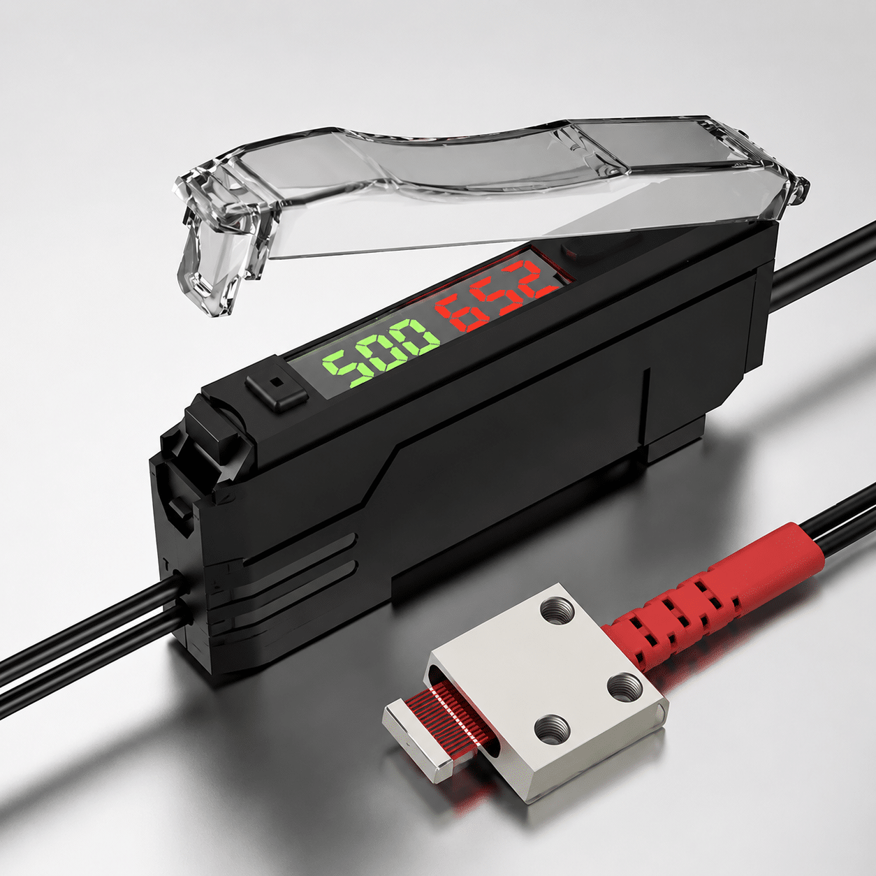
- Blanking and masking detection
- Ignore fixed machine areas
- Detect abnormal blockage
- Factory selection support
When the machine must ignore one area and detect another
Blanking detection is useful when normal optical sensing reacts to fixed brackets, expected material openings, product gaps or allowed movement that should not stop the machine.
Ignore fixed fixtures
Mask known brackets, guides, rails or tooling positions so the sensor focuses on the real detection condition.
Handle expected gaps
Reduce false triggering from permitted gaps, product spacing or repeatable openings in the sensing path.
Detect abnormal change
Trigger when an object appears outside the allowed blanking zone, a part is missing or a blocked area changes.
Built for special layouts where ordinary detection is too sensitive
Use fiber optic blanking sensors when the machine needs a controlled detection zone rather than a simple on/off object check.
Choose by the zone you want to ignore and the change you need to detect
For blanking sensors, the key is not only sensing distance. The key is understanding which area is allowed, which condition is abnormal and how the machine should respond.
| Selection Point | What to Confirm | Why It Matters | XSZ Support |
|---|---|---|---|
| Blanking zone | Area that should be ignored or masked | Prevents normal fixtures from causing false signals | Recommend blanking width and optical layout |
| Detection object | Abnormal blockage, missing part or unwanted object | Defines sensitivity and signal threshold | Match fiber head and amplifier setting |
| Target path | Movement direction, tolerance and product position | Prevents missed detection during real machine movement | Review photos, drawings and fixture dimensions |
| Environment | Dust, oil, vibration, ambient light and cleaning method | Affects signal stability over long production runs | Suggest protection and installation method |
| Output logic | NPN, PNP, NO, NC and controller input | Ensures the sensor works with the PLC or machine board | Help confirm wiring and response time |
Blanking sensor, matrix sensor or standard fiber sensor?
The best choice depends on whether you need to ignore a known area, monitor multiple positions or detect one fixed point.
Ignore expected areas
Choose blanking detection when fixed fixtures, allowed gaps or normal material openings should not trigger the output.
Multiple points or wider coverage
Choose matrix detection when the machine must monitor several positions, rows or a defined detection area.
One fixed sensing point
Choose a normal fiber optic sensor when one small target, edge or gap is detected at a stable location.
Common reasons blanking detection becomes unstable
Blanking applications often fail when the ignored zone is not clearly defined or the real abnormal condition is different from the test setup.
Blanking area too large
If too much of the detection zone is ignored, the sensor may miss a real abnormal object or missing part.
Target movement not checked
Product shake, conveyor variation or fixture tolerance can move the target outside the expected detection area.
Wrong output condition
Confirm whether the machine needs output when blocked, unblocked, missing, present, normal or abnormal.
Configure the sensor around the allowed and abnormal zones
Blanking sensors should be selected together with the mechanical layout, target movement and controller logic.
Blanking geometry
Define masked area, active area, detection width, optical path and allowed product tolerance.
Fiber head and cable
Confirm head style, cable length, bend radius, mounting direction and protection from vibration or abrasion.
Amplifier and output
Match sensitivity, response speed, teach mode, NPN/PNP output, NO/NC logic and PLC input voltage.
Send these details before choosing a blanking sensor
A good blanking solution starts from the real machine condition. Photos, drawings and target movement details help XSZ recommend the correct setup faster.
- Which area should be ignored during normal operation.
- Which condition should trigger output: missing, present, blocked or unblocked.
- Target size, material, color, reflectivity and movement tolerance.
- Mounting distance, bracket space, optical path and cable route.
- PLC input type, voltage, response speed and output logic.
| Application Detail | Recommended Check | Risk If Ignored |
|---|---|---|
| Allowed zone | Mark the normal ignored area on a photo or drawing | False trigger or missed abnormal object |
| Abnormal condition | Define exactly what must trigger the output | Wrong output logic in the machine |
| Fixture tolerance | Check vibration, product shake and position drift | Unstable signal during production |
| Machine speed | Match amplifier response time to cycle speed | Delayed output or missed detection |
| Environment | Review dust, oil, ambient light and cleaning method | Signal reduction after long use |
Mark the blanking zone. We help match the sensor setup.
Send XSZ a photo or drawing showing the allowed area and the abnormal condition. We can help select the fiber head, amplifier and wiring logic for your machine.
Show the layout
Send photos, drawings, target path, blocked area and fixture position.
Define the output
Confirm normal state, abnormal state, PLC input and response speed.
Confirm final model
Select the blanking sensor, amplifier, cable and mounting direction.
Manufacturer support for special blanking detection projects
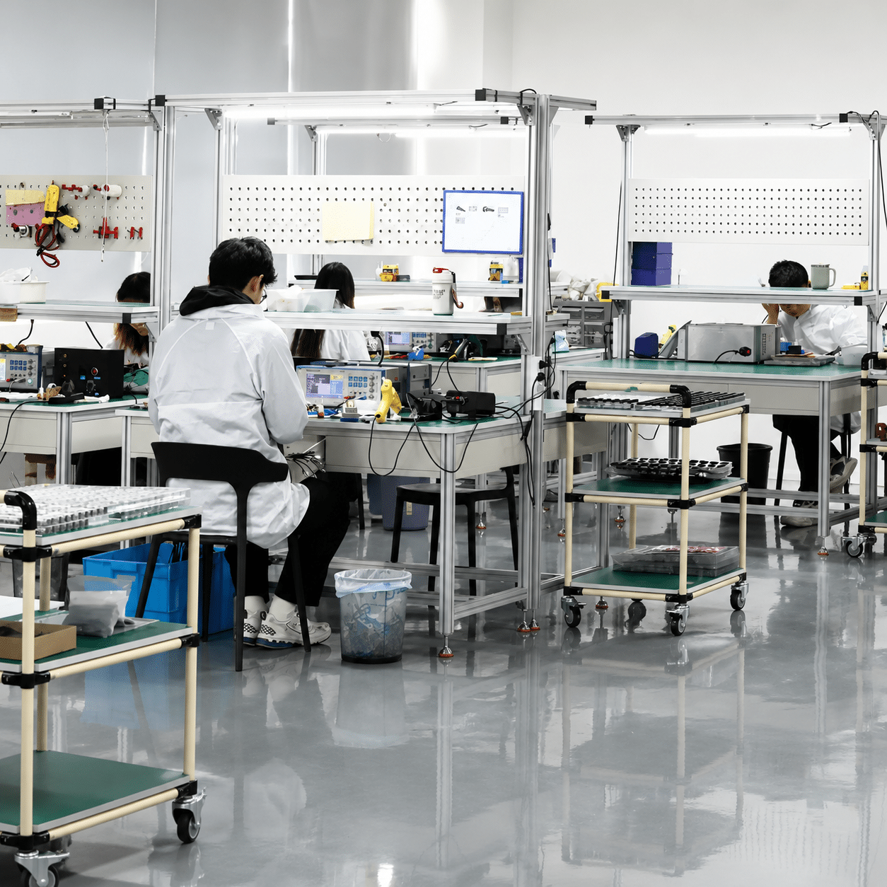
XSZ supports B2B buyers with application review, model selection, cable customization, labeling, packaging and stable supply for repeat machine builds.
Compare related fiber optic sensing options
If your machine does not need blanking, another fiber optic or photoelectric sensor may be simpler to install.