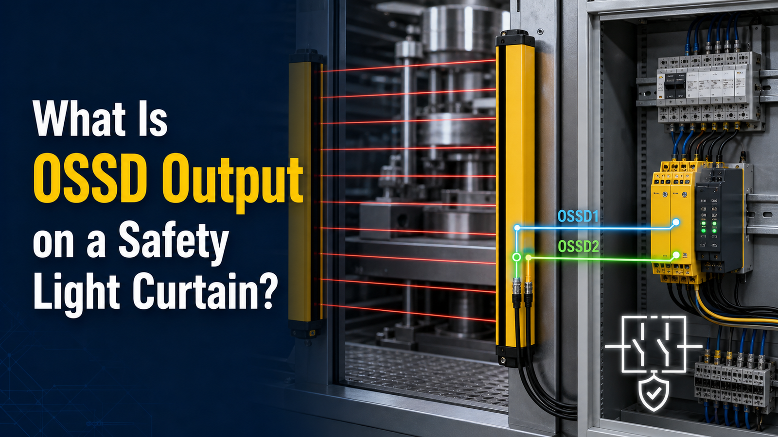
An OSSD output light curtain uses a self-monitoring, solid-state safety output that switches from ON to OFF the instant a beam is broken, as defined in IEC 61496. Unlike a standard relay, it fires diagnostic test pulses every few milliseconds to detect wire faults and short circuits. A typical OSSD sources 24 VDC when the field is clear and drops to 0 V[1] on intrusion, using dual channels (OSSD1 + OSSD2) for the redundancy required to reach PLe / SIL 3.
What are the dual-channel OSSD pair and the test pulses there for? And which parameters really matter when you wire an OSSD output light curtain into a safety PLC? Then, finally, what happens when a fault occurs?
Quick Takeaways
- OSSD outputs self-check for faults thousands of times per second automatically.
- Match test pulse duration with PLC input filter to avoid false trips.
- Wire OSSD1 and OSSD2 to separate PLC safety input channels.
- Faults trigger immediate OFF state, forcing a safe machine stop.
- Choose Type 4 curtains with OSSD outputs for highest-risk applications.
What Does OSSD Output Mean On A Safety Light Curtain?
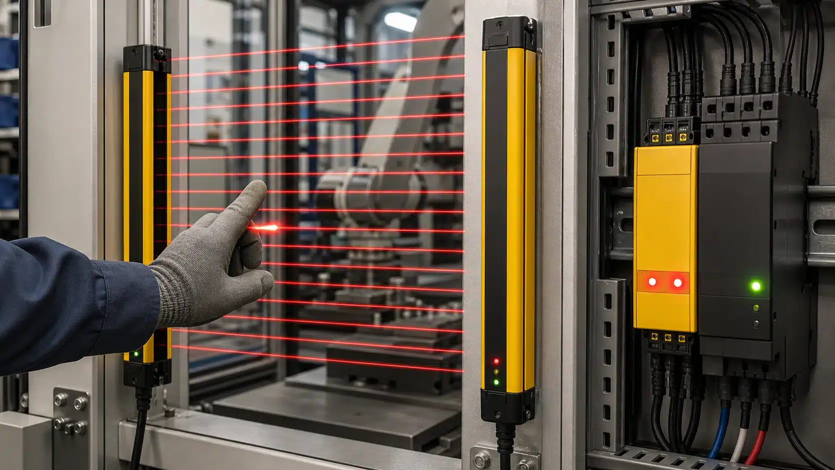
An OSSD output on a safety light curtain is a self-checking solid-state safety output that flips from ON to OFF the instant a beam gets broken. According to IEC 61496 as summarized on Wikipedia, OSSD stands for Output Signal Switching Device. It actually does more than simply carry a signal, because it constantly checks itself for problems.
Here is the important difference to understand. A plain digital output only tells you a state, meaning the beam is either clear or blocked. It has no way of knowing whether its own wiring shorted out or a transistor got stuck in the ON position. An OSSD, though, treats any hidden fault as something that could kill someone, so it searches for those faults thousands of times every second by sending out brief test pulses.
This is the reason Type 2, Type 3, and Type 4 light curtains rely on OSSD outputs rather than a simple relay contact. Type 4 devices, which sit in the highest safety class, are required to provide two OSSD channels, called OSSD1 and OSSD2, and both of them drop to OFF when something is detected. When the protected field being watched is clear, PNP-type OSSD outputs stay at 24 V[2]. On an intrusion, both channels fall to 0 V or high impedance, which essentially tells the machine to stop.
You can picture it like a smoke alarm that also tests its own battery every single second. A dead OSSD output light curtain basically announces its own failure by moving into the safe state, instead of quietly letting a hazard keep running. That self-diagnostic behavior is exactly the thing a plain signal wire can never really do.
How Do OSSD Safety Outputs Work Electrically?
OSSD outputs on a safety light curtain work as PNP sourcing transistors. When the protected field is clear, each channel actively drives 24 VDC to its load. The moment a beam breaks, both channels switch to 0 V (or high impedance). Per-channel current typically ranges from 100 to 500 mA in 2026 models, so most safety relays sit well inside that budget.
What Does “PNP Sourcing” Actually Mean Here?
PNP sourcing means the output supplies the positive voltage, not the ground. The transistor connects the load to +24 V[3], so current flows out of the OSSD terminal, through your safety relay input, and back to 0 V. The load’s negative side ties to system ground. This matters for wiring: a short to 0 V simply forces the output OFF, the fail-safe direction, while a short to 24 V[4] is the dangerous case, which is why cross-monitoring exists (covered next).
How Does the ON and OFF State Look on a Meter?
Probe an OSSD channel with a multimeter and the states are clear:
- Field clear (ON): reads near supply, typically 23–24 VDC, with a small transistor drop
- Beam broken (OFF): reads 0 V or floats to high impedance, commanding the machine to stop
- Current ceiling: stay under the rated 0.5 A per channel, or you risk thermal shutdown
Per IEC 61496, an OSSD output light curtain is defined as a self-monitoring solid-state output. That self-monitoring is why you never see a mechanical contact clicking, everything switches in solid-state silicon, in microseconds.
Why Do OSSD Outputs Use Dual Channels For Redundancy?
OSSD outputs on a safety light curtain use two independent channels, OSSD1 and OSSD2, so that no single component failure can leave a machine running when someone breaks the beam. Both channels switch OFF together on detection; if one fails but the other trips, the machine still stops. This dual-channel design is mandatory for Type 3 and Type 4 light curtains under IEC 61496.
How Do The Two Channels Mirror Each Other?
OSSD1 and OSSD2 run as two separate output circuits, each with its own transistor and internal logic. When the protected field is clear, both sit at 24 V. When a beam breaks, both drop to 0 V[5] within milliseconds. They are meant to be identical twins, same state, same timing. That mirroring is the whole point: a short circuit, a welded transistor, or a broken wire on one channel is a single fault, and redundancy means one fault alone can’t create a dangerous condition.
What Is Discrepancy Monitoring And Why Does It Matter?
Discrepancy monitoring watches whether both channels agree. If OSSD1 goes low but OSSD2 stays high past the allowed window (often a few milliseconds), the receiving safety controller flags a fault and locks the outputs OFF. This catches the dangerous single-channel failure before a second fault accumulates.
This is why you never jumper OSSD1 and OSSD2 together. Bridging them destroys the cross-check and drops your Performance Level. Wire each to a separate safety input.
What Are OSSD Test Pulses And Why Do They Matter?
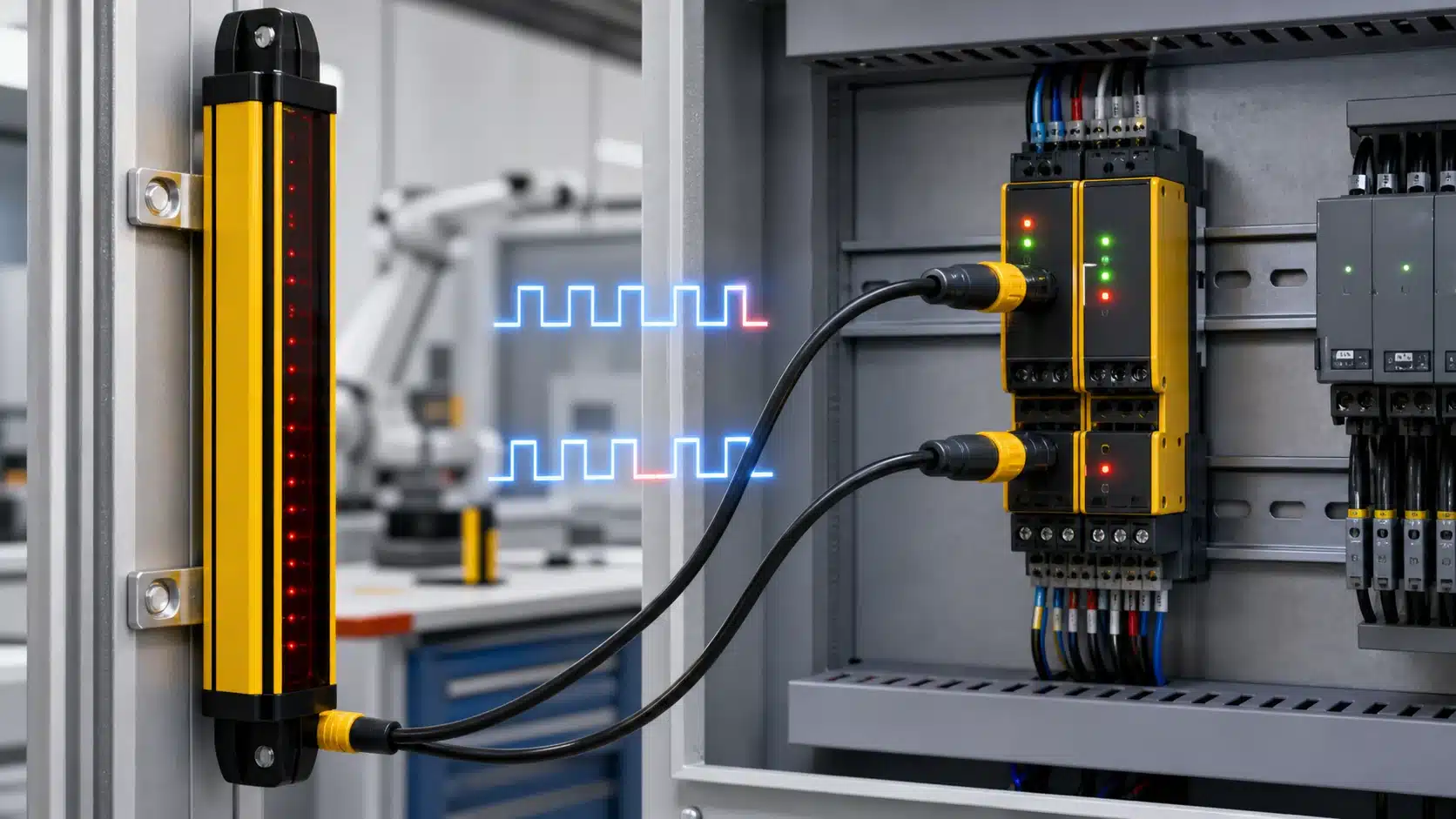
OSSD test pulses are microsecond-long OFF signals that each channel drops while the output stays ON. On an OSSD output light curtain, these pulses generally last around 200 microseconds up to a few milliseconds. They let the device catch wiring faults that would otherwise stay hidden, turning a “healthy-looking” output into one that proves itself thousands of times every second.
Here is how it works. The safe field is clear, so both channels sit at 24 V. But the controller briefly forces OSSD1 to 0 V for about 100 to 300 µs, then does the same thing to OSSD2 at a different moment. The two pulses never overlap, so each channel confirms it can actually switch OFF on command, and it does this without ever dropping the machine’s real stop signal.
Which Faults Do Test Pulses Actually Catch?
Test pulses expose three faults that plain outputs miss:
- Cross-short between channels: If OSSD1 and OSSD2 are shorted together, the 24 V[6] from one channel props up the pulse dip on the other. The controller then sees a pulse that never reaches 0 V, so the fault gets detected.
- Short-to-24V[7] (short-to-supply): A wire that has chafed against a +24 V line holds the output high permanently. The expected OFF pulse vanishes, so the light curtain locks out.
- Stuck-on output: A welded transistor can’t pull low during its test window. The missing pulse flags a dangerous failure before the machine ever relies on it.
This self-test is really why IEC 61496 lets OSSD outputs reach Category 4 without an external checker for these particular faults. If you skip a controller that filters pulses correctly, you basically lose the very diagnostics you paid for.
How Should Safety PLC And Relay Inputs Be Configured To Ignore Test Pulses?
Safety inputs must be set with a pulse-tolerance filter longer than the OSSD test pulse but shorter than any real stop signal. Since OSSD outputs on a safety light curtain drop OFF for roughly 200 microseconds to a few milliseconds per test cycle, the input must ignore those brief dips. Set filtering right and the machine keeps running; set it wrong and you get false trips or missed faults.
⚠️ Common mistake: Configuring the PLC input filter too short, so it catches the OSSD’s diagnostic test pulses (typically 100–300 µs every few milliseconds) as real signal drops, causing random nuisance trips. This happens because the pulses briefly force the 24 V line to 0 V[8] for self-diagnosis. The fix: set the PLC input filter longer than the test pulse width but shorter than your response-time budget.
How Do You Set The Input Filter Time Window?
The filter window should sit between the test pulse width and the real intrusion response time. A common rule: filter above 700 microseconds to swallow a 200-microsecond pulse, but well below the light curtain’s response time (often 10,30 milliseconds). Most safety PLCs, like those following IEC 61508, offer a configurable “input filter” or “test pulse filter” parameter per channel. Match this to the light curtain datasheet value.
What Happens When Filtering Is Mis-Set?
Two failure modes appear. Set the filter too short, and the controller reads each test pulse as a stop command. This causes nuisance trips: the machine halts every few hundred milliseconds for no real reason, and operators start bypassing the guard.
Set the filter too long, and the input masks genuine faults. A real short circuit between OSSD1 and OSSD2 lasting several milliseconds gets filtered out, so the stop never fires. That defeats the cross-monitoring the dual channels were built to provide. Always verify the window against the manufacturer’s stated pulse timing, never a generic default.
How Do You Connect OSSD Outputs To Safety Relays And Safety PLCs?
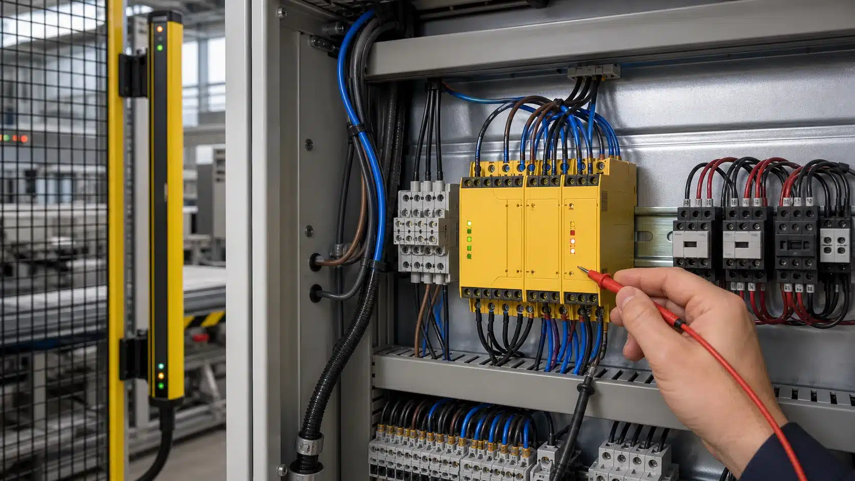
Wire OSSD1 and OSSD2 to two separate safety input channels, and never jumper them together. Standard practice requires each channel of an OSSD output light curtain to land on its own input so the receiving device can run cross-fault monitoring, per common OSSD wiring guidance. This lets the system catch a short between the two wires and force a stop.
How Do You Terminate Dual Channels With Cross-Fault Monitoring?
Land OSSD1 on safe input A and OSSD2 on safe input B. Cross-fault monitoring means the device watches whether the two channels ever match wrongly (both stuck ON, or one shorted to 24 V). If a screwdriver bridges the two wires, the monitored device sees the fault and locks out. Add a reset circuit: a normally-open push button wired to the reset input, so the machine only restarts after a deliberate press.
When Do You Use A Safety Relay Versus Direct Safe Inputs?
Use a safety relay module when your machine controller isn’t safety-rated. The relay accepts both OSSD channels, adds external device monitoring (EDM) to check contactor feedback, and drives two redundant contactors. Use direct safe-input terminals on a safety PLC when you already run one; it handles pulse tolerance, EDM, and reset logic in software, cutting hardware cost.
| Interface | Best For | Cross-Fault Detection | Reset Logic |
|---|---|---|---|
| Safety relay module | Non-safe machine controllers | Built into module | Hardware button |
| Safety PLC safe inputs | Existing safety network | Configured in software | Program logic |
Both paths must meet the required Performance Level (PLr) through certified dual-channel monitoring.
How Do OSSD Outputs Compare To PNP, Relay, And Antivalent Outputs?
OSSD outputs win over standard PNP, relay, and antivalent outputs because they self-test continuously and detect their own faults. A standard PNP transistor can’t tell if it welds ON. An OSSD output on a light curtain injects 200-microsecond test pulses so a short circuit or stuck output is caught within milliseconds. That’s why OSSD is the default for PL d and PL e systems under IEC 61496.
| Output type | Fault detection | Max safety rating | Wiring |
|---|---|---|---|
| OSSD (dual PNP + pulses) | Self-monitoring, cross-fault | PL e / SIL 3 | Two channels, no jumper |
| Standard PNP | None | Not rated | Single wire |
| Relay (mechanical) | Only with forced-guided EDM | PL c–d | Contacts + feedback loop |
| Antivalent (complementary) | Plausibility only | PL d | One NO + one NC channel |
Antivalent outputs run one channel ON while the other stays OFF, and the receiving device checks that the two never match. That catches wiring faults, but it misses the dangerous short circuits that OSSD test pulses expose, hence its lower PL d ceiling in the table. Relays add slow switching and contact wear, so they can’t reach the diagnostic coverage OSSD delivers.
Skip standard PNP for guarding. Use it only for status lamps or PLC signals, never for stopping a machine.
How Do You Diagnose OSSD Faults And Reset A Fault-Lock State?
Read the status LEDs first. On an OSSD output light curtain, a fault lock is signaled by a specific LED pattern (usually a flashing red on the receiver), and it won’t clear on its own. Since IEC 61496 requires self-monitoring, the curtain deliberately traps itself in a safe OFF state until you fix the fault and reset it.
What Do The Fault LED Patterns Actually Mean?
Three faults trigger a lock, and each shows a distinct code:
- Cross-fault: OSSD1 and OSSD2 shorted together. The curtain sees the test pulses collide and locks out — this is why you never jumper the channels.
- Short-to-supply: One OSSD line touching 24 V. The output can no longer be forced to 0 V[9], so it fails safe.
- Stuck-on: The internal transistor won’t switch OFF during a test pulse. The curtain flags an output overcurrent (often past the 100–500 mA per-channel limit) and locks.
How Do You Reset After A Cross-Fault?
A fault lock never clears by simply clearing the field. You must remove the physical cause first, repair the wiring short or replace a damaged cable. Then power-cycle the curtain (24 V off for at least 2 seconds, then on), or press the manual reset if the model supports it. If the LED still flashes, the fault remains.
Quick checklist: (1) note the LED code; (2) meter OSSD1 and OSSD2 for continuity between them (should be open); (3) check each line against 24 V; (4) confirm current draw is under spec; (5) repair, then power-cycle.
Frequently Asked Questions About OSSD Light Curtain Outputs
Short answers to the questions installers ask most about OSSD output light curtain wiring, current limits, and fault behavior. Each one below is based on IEC 61496 requirements and real product specs.
Can OSSD Outputs Drive Contactors Or Solenoids Directly?
No. OSSD outputs can’t switch a contactor coil directly. Most channels are limited to under 200 mA at 30 VDC, and many models cap at 100,500 mA depending on the unit, per 2026 industrial sensor specs. A contactor coil often pulls 300,600 mA inrush, which overloads the solid-state output. Route OSSD1 and OSSD2 into a safety relay or safety PLC, then let its force-guided relays switch the contactors.
What Happens If Only One OSSD Channel Triggers?
A single-channel switch usually means a fault, not a valid stop. The two channels are cross-monitored, so if OSSD1 drops to 0 V[10] while OSSD2 stays at 24 V for longer than the discrepancy time (often 5,100 ms), the light curtain enters a fault-lock state. A correct intrusion drops both channels together within milliseconds.
Does An OSSD Output Need An External Test Signal?
No. OSSD outputs self-test internally with built-in OFF test pulses of roughly 200 microseconds to a few milliseconds. You don’t supply an external test signal. The receiving safety controller just needs pulse-tolerance filtering set longer than those pulses so it does not read them as a stop command.
Key Takeaways For Working With OSSD Safety Outputs
An OSSD output light curtain is a self-monitoring solid-state safety output that switches from ON to OFF when a beam is broken, and it constantly tests itself to catch its own faults. Per IEC 61496, this fault-detecting behavior is what separates a true safety output from an ordinary switch.
The whole design rests on two ideas. Dual channels (OSSD1 and OSSD2) give redundancy, so one failed channel never leaves the machine running unsafely. Test pulses,short OFF blips around 200 microseconds,let the connected controller spot short circuits and cross faults between wires. Break either one, and the output locks OFF.
Before you power up, run this checklist:
- Separate inputs: Wire OSSD1 and OSSD2 to two distinct safety input channels—never jumper them together.
- Pulse filter: Set the safety input’s pulse-tolerance window longer than the OSSD test pulse to prevent false trips.
- Current budget: Confirm your load stays inside the rated per-channel current, often 100–500 mA at 24 VDC.
- EDM feedback: Monitor the contactor mirror contacts so a welded output is detected on the next cycle.
- Certified device: Connect only to a safety relay or safety PLC rated for your required Performance Level.
One rule beats all guesswork: verify every setting against the safety controller manual. Pulse width, input mode, and PLr requirements vary by model, and the manufacturer’s document is the only authority that keeps your wiring compliant.




