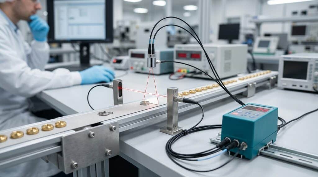
Fiber amplifier setup guide
Fiber Optic Sensor Teach Mode: Sensitivity Setup Explained
Teach mode records one or more received-light conditions and uses them to set a switching point or switching window. The best mode depends on whether the target moves, whether both target and background can be presented, and how much the signal varies during production.
- One-point, two-point, dynamic and window teach
- Low-contrast and moving target setup
- Teach-error diagnosis and maintenance records
For most stationary applications, start with two-point teach using the real target and real background. Use dynamic teach when the signal must be sampled while the line is moving.
The amplifier stores light levels seen through the selected fiber head. It does not learn the object name, color, or material directly.
Teach determines thresholds. Light-ON or Dark-ON determines which signal condition turns the output on.
Button timing, teach-point order, indicator colors, error codes and threshold formulas vary by amplifier model.
Know what the amplifier stores
Teach mode learns signal conditions, not the target itself
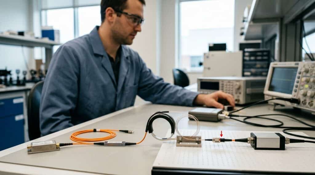
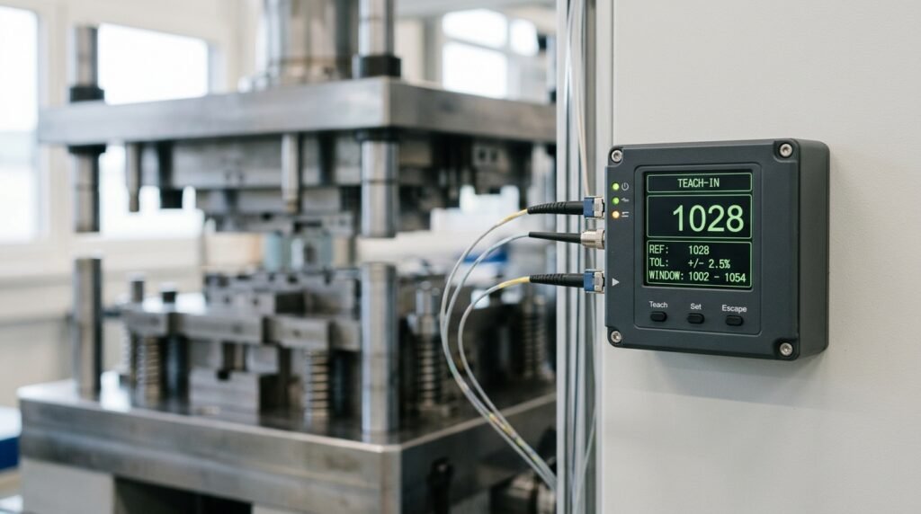
A fiber optic amplifier sends light through a fiber, measures the light returning to its receiver, and converts that measurement into an internal received-light value. During teach, the amplifier stores one value, two values, or a range of values depending on the selected mode.
The amplifier then calculates one or two switching points. During RUN mode, the live received-light value is compared with those points to determine the output state. This is why a teach performed on a workbench can fail after installation: the final distance, angle, fiber bend, target motion, background, contamination and ambient light may produce a different signal.
From light to PLC signal
How does a fiber optic amplifier create a teach threshold?
The exact internal algorithm is manufacturer- and mode-specific, but the engineering chain is consistent: create a light path, sample realistic conditions, calculate switching behavior, and verify the output over production variation.
The amplifier drives the light source and couples it into the transmitting fiber.
The object blocks, attenuates, reflects or redirects light according to the fiber arrangement.
The receiving fiber returns light to the amplifier, which displays or stores a received-light value.
One-point, two-point, dynamic or window logic uses different numbers of teach points.
The live value is compared with the switching point or window and the configured output logic.
Match the mode to the process
Which fiber optic sensor teach mode should you use?
Mode names are not standardized across every amplifier. Use the descriptions below to identify the required behavior, then confirm the corresponding menu name and teach sequence in the exact manual.
Two-point static teach
Stores two stable conditions, normally target present and target absent, then calculates a switching point between them.
- Use when both conditions can be presented separately.
- Good for stationary or indexed parts.
- Verify whether the manual permits either teach-point order.
Dynamic or full-auto teach
Samples the live signal while multiple targets and gaps pass, then derives switching behavior from the recorded range.
- Use for moving webs, bottles, edges or variable passing positions.
- Run at the real speed and include representative variation.
- Do not include abnormal product or long empty intervals unintentionally.
One-point, light set or dark set
Stores one condition and places a switching point at a model-specific offset from that value.
- Useful when contrast is strong and only one condition is easy to present.
- Offset direction must match the expected signal change.
- Avoid assuming the offset is always 50 percent.
Window teach
Creates two switching points from two taught conditions so the amplifier can detect values inside or outside a defined range.
- Useful for position bands, dimensional checks or controlled signal ranges.
- Not automatically the best choice for every transparent target.
- Confirm inside-window versus outside-window output behavior.
Zone or percentage teach
Builds a window around one taught reference using a configured positive and negative offset.
- Useful when a reference condition should remain within tolerance.
- The allowable offset is model-specific.
- Test normal product variation before narrowing the zone.
Manual threshold adjustment
Lets the technician observe received-light values and move the switching point directly rather than running an automatic teach.
- Useful for controlled commissioning and unusual signal distributions.
- Document the final threshold and output logic.
- Protect the setting with key lock or access control where supported.
| Teach behavior | Conditions sampled | Best process fit | Main setup risk |
|---|---|---|---|
| Two-point static | Two separately presented states | Indexed, stopped or manually presented targets | Teaching a clean sample that does not represent production variation |
| Dynamic / full-auto | Minimum, maximum or multiple values during a time window | Continuous motion, flutter, varying reflection or passing edges | Capturing the wrong products, speeds or empty gaps during teach |
| One-point / set | One reference plus a configured offset | Strong contrast and one easily presented condition | Wrong offset direction or too little margin for the unseen condition |
| Window / zone | Two boundaries or one reference plus tolerance | Acceptable ranges, position bands and change monitoring | Window narrower than normal target, vibration or temperature variation |
Some amplifiers also offer power tuning, maximum-sensitivity tuning, position tuning, differential detection, automatic drift compensation or IO-Link parameter management. These functions are not equivalent to a universal teach standard.
A repeatable commissioning method
How do you run teach mode and verify the result?
The button sequence comes from the model manual. The workflow around that sequence can be standardized so the taught setting represents the real machine rather than a convenient sample.
-
Identify the exact amplifier and fiber arrangement
Record the amplifier model, firmware if relevant, reflective or through-beam fiber type, output version, current response mode and Light-ON/Dark-ON setting.
Do not use a button sequence copied from another amplifier family. -
Prepare the final optical geometry
Install the fiber heads at the production distance and angle, respect bend radius, secure the brackets, clean the end faces and remove protective film or debris from the light path.
-
Observe target and background values
Run representative samples and note the received-light values for good product, empty background and relevant variations. Check for saturation as well as insufficient light.
-
Select the teach behavior
Use two-point for two stable states, dynamic for moving variation, one-point for a strong reference with a known offset, or window/zone for a controlled band.
-
Perform teach exactly as the manual specifies
Follow the required point order, button duration, remote-input timing or IO-Link command. Confirm that the amplifier returns to RUN mode without a teach error.
-
Verify output logic and switching margin
Cycle real parts, empty spaces and boundary cases. Confirm the PLC sees the intended state and that Light-ON/Dark-ON, NPN/PNP and NO/NC behavior match the control logic.
-
Test worst-case production variation
Check normal speed range, target position, surface variation, lighting, vibration, machine warm-up and expected contamination. A successful teach is only the beginning of validation.
-
Lock and document the approved setting
Record teach mode, live signal values, switching point or window, response mode, output logic and test result. Apply key lock or access control if supported.
Interactive planning aid
Which teach method fits your application?
Select the process conditions to identify a practical starting method. The result describes the teach behavior to look for in your amplifier manual.
This selector is a setup-planning aid. It does not confirm amplifier compatibility, achievable contrast, response time or final process capability.
Two-point static teach
Teach the real target and real background as two separate conditions, then verify the resulting switching point over production variation.
- Record both received-light values before teaching.
- Confirm teach-point order in the exact manual.
- Validate output over repeated cycles.
Improve the optical problem first
How should you teach transparent, glossy, small or fast targets?
Difficult targets often need a better fiber type, wavelength, geometry or response mode before they need a tighter threshold. Teach cannot create contrast that the optical arrangement does not produce.
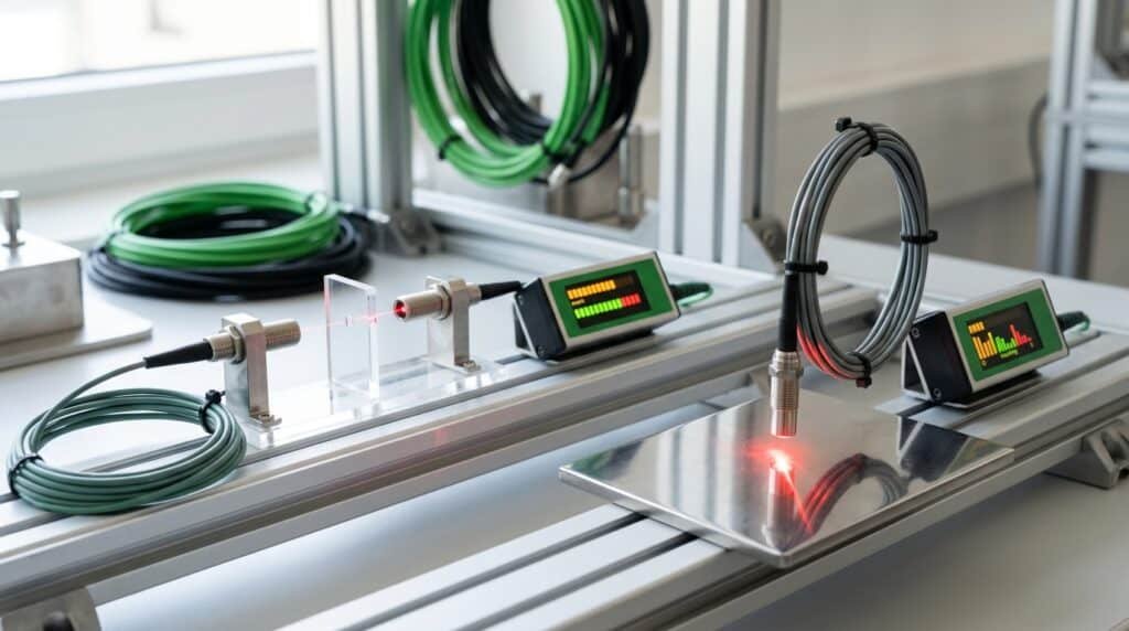
- Transparent bottles, film or glass Through-beam geometry often gives a clearer attenuation measurement than diffuse reflection. Test lens effects, target position and wavelength options supported by the amplifier and fiber.
- Glossy or mirror-like surfaces Watch for saturation and sharp specular peaks. Change the fiber angle, increase background separation or choose a geometry designed for the surface before narrowing the threshold.
- Very small parts or edges Confirm that the beam or sensing area is appropriately sized and that the target crosses the most repeatable part of the field. Coaxial, focused or through-beam fibers may help depending on the task.
- Fast, fluttering or position-varying targets Use dynamic sampling at real speed and choose a response mode fast enough for the target duration. Faster response can reduce optical gain or filtering, so validate both speed and margin.
- Dark or low-reflectivity targets Reduce distance, improve alignment, select a higher-power mode if timing allows, or change the fiber arrangement. Avoid maximum sensitivity when it also captures unstable background light.
Troubleshoot the cause, not the code alone
Why does fiber optic sensor teach mode fail?
The most common failure is insufficient separation between the taught signal conditions. Error numbers and LED patterns vary, so use the exact manual while checking the optical and process causes below.
| Symptom | Likely cause | Engineering check | Practical correction |
|---|---|---|---|
| Teach error or low contrast | Target and background values are too close for the selected mode. | Compare live received-light values and confirm both teach conditions were actually presented. | Change distance, angle, background separation, fiber type or sensing mode before repeating teach. |
| Value is saturated | Too much light reaches the receiver, hiding useful variation. | Check the display for maximum value across both conditions and inspect reflective surfaces. | Reduce transmitter power, increase distance, change geometry or select a lower-gain/faster mode if the manual supports it. |
| Stable teach, unstable production | The taught samples did not include vibration, speed, position, surface or lighting variation. | Trend the live value while the machine runs at normal limits. | Improve mounting and optical margin, then use dynamic teach or a more representative static sample set. |
| Output works in reverse | Light-ON/Dark-ON, NPN/PNP or controller logic does not match the intended condition. | Watch the amplifier output indicator and PLC input for target and no-target states. | Correct output logic or wiring; do not keep re-teaching an already valid threshold. |
| Window teach rejected | The two boundaries are too close or were taught in the wrong sequence. | Check the manual's minimum window and point order. | Increase separation between taught conditions or use a zone/offset method if supported. |
| Buttons do not respond | Key lock, remote teach control, IO-Link state or menu access is active. | Check lock status, input wiring and communication state. | Use the documented unlock or remote configuration procedure rather than a generic long-press reset. |
Three settings that are often mixed together
Threshold, hysteresis and response time solve different problems
Decides where switching occurs
The switching point separates signal conditions. Move it only after confirming the target and background distributions. A midpoint can be useful for two clearly separated states, but it is not a universal optimum for every process.
Prevents output chatter
Hysteresis creates separation between the output's turn-on and turn-off behavior. Too little can chatter near the threshold; too much can hide small changes. The available adjustment and units are model-specific.
Balances speed and optical margin
High-speed modes can detect shorter events, while longer-response or higher-power modes may improve weak-signal performance. Select from the exact amplifier data and verify the target dwell time at maximum line speed.
Model-specific visual example
See how dynamic teach is performed on a fiber amplifier
This official manufacturer video demonstrates dynamic teach on a Banner DF-G fiber optic amplifier. Use it to understand the workflow, then follow the manual for the amplifier installed on your machine.
How-To Guide: DF-G Dynamic Teach
The video covers the basic mode selection and dynamic sampling sequence for the DF-G amplifier family. Button labels and menus shown in the video do not automatically apply to another brand or model.
Open the official videoMake the setup repeatable
What should maintenance record after teaching?
A useful record lets another technician identify drift, replace an amplifier, or compare two stations without repeating trial-and-error setup.
- Clean without hiding drift Inspect and clean fiber tips according to the fiber material and manual. Compare live values with the approved baseline before deciding to re-teach.
- Re-teach after relevant changes Re-teach when the fiber, position, target, background, response mode or optical geometry changes, or when the documented process requires it.
- Avoid arbitrary calendar intervals There is no universal three- or six-month teach interval. Base checks on contamination rate, process risk, maintenance history and the model instructions.
- Investigate a falling signal first If the live value moves away from the approved baseline, inspect contamination, bends, damage, alignment and target variation before teaching the degradation into a new threshold.
- Validate replacement units Copied parameters can speed setup, but the replacement amplifier and fiber path still need live signal and output verification on the actual machine.
Prepare a useful application review
Need help matching the amplifier, fiber head and teach method?
Send the target and background photos, smallest target size, sensing distance, fiber mounting drawing, line speed, current received-light values, desired output logic, supply voltage, environment and quantity. XSZ can help compare suitable fiber amplifier and cable configurations for testing.
Frequently asked questions
Fiber optic sensor teach mode FAQ
What does teach mode do on a fiber optic sensor?
Teach mode stores one or more received-light conditions and uses them to set a switching point or switching window. The fiber amplifier then compares the live signal with those settings during RUN mode.
Should I teach the target or the background first?
It depends on the amplifier and mode. Some two-point modes allow either order, while other models or remote-teach procedures require a defined sequence. Follow the exact manual and record which condition was used for each teach point.
When should I use dynamic teach instead of two-point teach?
Use dynamic teach when the signal changes because the target moves, flutters, rotates, changes angle or passes at different positions. Run the process at representative production speed and make sure the sampling interval contains the correct target and background events.
Is the threshold always set halfway between target and background?
No. Some two-point modes use an average, but one-point, window, zone, power-tuning and manufacturer-specific optimization modes use different logic. Treat midpoint behavior as a model example, not a universal rule.
Why does the amplifier show a teach error?
A common cause is too little difference between the taught received-light values. Other causes include saturation, incorrect teach-point order, a window that is too narrow, key lock, remote-input state or model-specific setup errors. Check the error table in the exact manual.
Is more sensitivity always better?
No. Higher sensitivity can also increase the influence of background reflections, contamination, vibration and optical noise. The goal is stable separation between valid process conditions with enough response speed, not the largest possible display value.
How often should a fiber optic sensor be re-taught?
There is no universal calendar interval. Re-teach after relevant changes to the fiber, mounting, target, background, response mode or optical geometry, and when required by the validated maintenance procedure. Investigate contamination or damage before teaching a degraded signal as the new normal.
Can teach mode fix detection of a transparent or glossy target?
Teach can optimize switching only when the optical arrangement creates repeatable signal separation. Transparent and glossy targets may first require different geometry, fiber type, wavelength, distance, background control or response mode.
Technical references
Primary sources used for this guide
-
01
SICK WLL80 operating instructions Definitions and model examples for one-point, two-point, dynamic, zone and window teach-in, plus teach-error diagnosis.
-
02
Omron E3X-HD Smart Tuning features Official example of a fiber amplifier that uses workpiece and no-workpiece tuning to set incident level and threshold.
-
03
Omron E3X-ZV / MZV specifications Current amplifier example showing multiple tuning methods, manual adjustment and selectable response modes.
-
04
Banner DF-G3 fiber optic amplifier Official product reference for TEACH and SET methods, hysteresis control and fiber-amplifier setup resources.
-
05
SICK transparent bottle application note Application evidence showing how wavelength and target optics can change signal quality for filled transparent bottles.