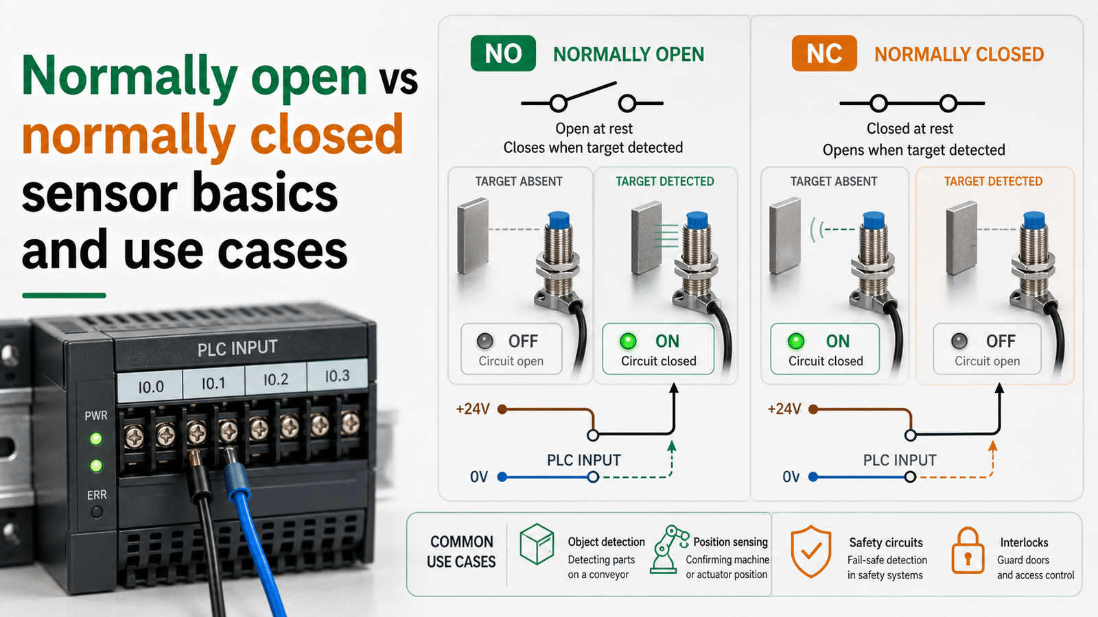
The core difference in a normally open vs normally closed sensor is the resting output state: a normally open (NO) sensor stays non-conducting until a target enters the sensing field, while a normally closed (NC) sensor conducts by default and opens when a target appears. For example, most PLC start buttons use NO contacts, whereas emergency stops use NC per IEC 60204-1, since a broken wire in an NC circuit triggers a fail-safe stop. Both types share identical sensing ranges—only the output logic flips.
This guide walks through what each type does, how NO and NC differ when it comes to wiring and fail-safe behavior, which one is a better fit for safety circuits, and how you can pick the right contact type for your particular machine.
Quick Takeaways
- NO sensors stay open at rest, closing only when detecting a target.
- NC sensors conduct by default, opening the circuit upon target detection.
- Choose NC for emergency stops so broken wires trigger fail-safe shutdowns.
- “Normally” describes the resting state, not the moment of detection.
- Verify NO/NC labeling before wiring to prevent common machine faults.
What do normally open and normally closed mean in a sensor output?
Normally open (NO) and normally closed (NC) describe the resting state of a sensor’s switching element back when the sensor sees no target and no push has happened. A 2025 proximity sensor reference confirms that an NO output sits non-conducting, meaning open, when there is no target present, and then it closes and turns ON once a target enters the field. NC does the opposite of that. So NO essentially gives you a signal only when it gets triggered, while NC gives you a signal right up until the moment it is triggered.
Here is the spot where people tend to trip up. The word “normally” always points to the resting state, so that means no object, no push, and no motion at all. It does not describe the actual moment of detection. A normally open contact reads open when nothing is happening, and then it snaps closed when the target finally arrives. Mix up those two ideas, and your logic ends up running completely backward.
A simple inductive proximity switch makes this whole thing clear:
- NO proximity switch: acts like a household light switch, so it stays off by default and sends voltage only when metal enters the sensing zone, which is typically 2 to 8 mm[1] for standard M12 inductive types.
- NC proximity switch: acts like a safety breaker, so power flows by default, and then it cuts off the instant the target gets detected.
The core rule for the normally open vs normally closed sensor choice comes down to this. NO “works,” meaning it turns ON, when it detects the target, while NC “works,” meaning it stays ON, when nothing is sitting there. That single distinction actually drives every wiring and fail-safe decision you will run into in the later sections.

How do NO and NC sensors behave in normal operation versus a fault condition?
In the normally open vs normally closed sensor comparison, an NO output stays silent (no signal) until a target arrives, while an NC output pushes a live signal by default and drops it when triggered. The split matters most during a fault: a wire break kills current in both, but only the NC circuit reads that loss as a real alarm. Think of NC as a safety breaker that cuts power when a problem shows up.
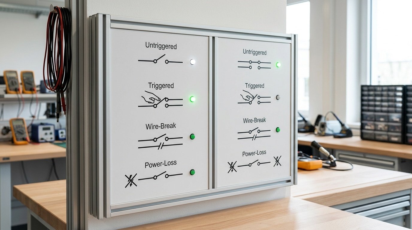
Each type moves through four states. Here is the side-by-side breakdown:
| State | NO output | NC output |
|---|---|---|
| Untriggered (no target) | OFF (open, no signal) | ON (closed, signal present) |
| Triggered (target detected) | ON (closes, sends signal) | OFF (opens, signal drops) |
| Wire-break fault | OFF — looks identical to “no target” | OFF — reads as an alarm |
| Power-loss fault | OFF — silent, no warning | OFF — controller sees fault |
The trap sits in row three. An NO circuit produces zero signal whether the target is absent or the cable is cut, the controller can’t tell the difference, so a severed wire hides behind a normal-looking “nothing detected.” That is why automation guidance in 2024,2025 favors NC outputs for fail-safe monitoring: any loss of the resting signal flags a fault instantly.
This four-state logic is the backbone of the fail-safe framework covered next, where wire-break and power-loss behavior decide which design keeps machines safe.
What happens when the wire breaks or power is lost on each type?
A broken wire will quiet down both types of sensor, but only a normally closed (NC) loop treats that silence as a problem. When you compare a normally open vs normally closed sensor with a cut cable, the NC contact loses the ON signal it normally holds, so the controller trips and stops things. An NO loop just stays quiet, and that quiet looks exactly the same as “no target present.” This is basically why safety guidance in 2024,2025 favors NC outputs for fail-safe monitoring.
Consider three ways things can go wrong. With a cut cable the circuit opens, so NC drops its signal and the system reads it as a fault, while NO shows nothing at all and the failure goes unnoticed. With a loose terminal you get intermittent contact, so NC flickers and trips, which warns you something is off, though NO might never send a signal in the first place. With a blown supply the power is gone, so NC de-energizes and trips, while NO simply cannot switch on when a real target actually shows up.
What’s de-energize-to-trip logic?
De-energize-to-trip means the safe state happens when power is lost, rather than when power is applied. During normal running the circuit carries current the whole time, a bit like a pilot light that stays lit. Cut that current through a break, a disconnection, or a supply loss, and the machine stops on its own. Because any hardware fault takes away power, those faults automatically push the system toward the safe condition instead of leaving it in silent danger.
Why accept NC despite nuisance trips?
NC contacts do trip on vibration, corrosion, or marginal wiring, which gets annoying on a busy production line. Still, a nuisance stop only costs you a few minutes, though an undetected NO failure can cost someone a hand. That trade-off is really the reason interlocks and emergency stops default to NC in the first place.
NO vs NC — which is safer for guarding and interlocks?
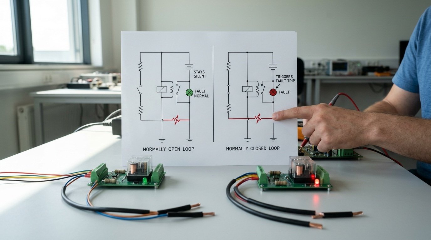
When it comes to machine guarding and interlocks, the normally closed (NC) type is the safer choice. An NC contact keeps the safety circuit powered up while the guard stays shut, and then it opens the instant the gate lifts or a wire happens to fail. Because 2024 automation guidance shows that a broken wire causes the signal to drop, that particular fault gets read as “stop”, so the machine moves itself into a safe state on its own.
Now compare that behavior to a normally open output. In the normally open vs normally closed sensor debate, the NO contact only sends the “safe” message once it actually closes. So if the wire snaps or a contact welds itself shut, the guard could appear closed even though it is really wide open. That kind of silent failure is exactly the thing that safety standards forbid.
Why do standards demand positively-driven NC contacts?
Positively-driven contacts, which are also called “force-guided”, have a mechanical link that physically pries them open. A welded contact simply cannot lie about its state. The ISO 14119 interlock standard favors this design because it makes any failure detectable rather than keeping it hidden.
What’s dual-channel monitoring for interlocks?
Dual-channel means that two independent NC circuits are both watching the same gate at once. A safety relay then compares the two signals against each other. If one channel opens but the other one stays closed, which is a fault, the relay refuses to reset. Light curtains and safety gates rated to SIL 3 or PLe rely on this cross-check so they can catch a single fault before a second one has the chance to hide the danger.

Which type should I use for safety gates, e-stops, alarms, and PLC inputs?
Use normally closed (NC) for anything that must fail safe: e-stops, safety gates, and fire alarms. Use normally open (NO) for start and pilot functions where an accidental fault should never trigger the action. In the normally open vs normally closed sensor debate, the rule is simple: NC when signal loss should stop the machine, NO when signal loss should do nothing.
Why the split? NC outputs are chosen for fail-safe monitoring because a broken wire drops the signal, and the system reads that dropout as a fault, per automation engineering guidance. That is exactly what you want on a stop circuit and exactly what you don’t want on a start button.
| Application | Contact type | Failure-consequence reason |
|---|---|---|
| Emergency stop | NC (mandatory) | Wire break stops the machine, matching ISO 13850 |
| Safety gate interlock | NC | Open gate or cut wire both halt motion |
| Fire alarm loop | NC | Broken line reads as alarm, never silent failure |
| Start / pilot button | NO | Fault can’t self-start the machine |
| General PLC sensing input | NO (typical) | Object present = ON, easy to program and troubleshoot |
For e-stops, NC isn’t a preference. The ISO 13850 standard requires a positive-opening NC contact so the stop works even if the switch mechanism jams. For everyday counting or position sensing feeding a PLC input, NO stays the default choice.
How do you wire NO and NC proximity and contact sensors?
Wire NO and NC sensors by matching the output type to your PLC input. Three-wire proximity sensors run brown to +24V[2] DC, blue to 0V[3], and black as the switched signal. Two-wire dry-contact devices like reed and limit switches simply break the load circuit. Some proximity sensors even supply both NO and NC on separate terminals (antivalent outputs), so one device covers either logic without hardware swaps.
What’s the difference between PNP (source) and NPN (sink) wiring?
PNP sensors switch the positive line and source current into the load; NPN sensors switch the negative line and sink current from it. A PNP output connects the load between the black signal wire and 0V[4]. An NPN output connects the load between +24V and the black wire. Match this to your PLC input card: sinking inputs need PNP sensors, sourcing inputs need NPN.
Where does the load go on two-wire versus three-wire sensors?
On two-wire reed and limit switches, the load sits in series with the switch contacts, so leakage current in the off-state matters. Three-wire sensors keep the load separate from the sensor’s own power, giving cleaner signals. For the normally open vs normally closed sensor choice, the same physical proximity sensor with antivalent terminals lets you rewire from NO to NC by moving one wire,no new part needed.
How do you test NO and NC contacts with a multimeter and in PLC logic?
Set your digital multimeter to continuity mode, then probe the contact at rest. A resting NC contact beeps and shows near-zero ohms (a closed path), while a resting NO contact stays silent (open path). This 5-second check tells you which type an unmarked sensor is before you wire anything.
What does the bench test sequence look like?
Follow four steps to confirm state at rest and under actuation:
- Power off, disconnect the sensor. Testing a live output can read the load, not the contact.
- Continuity at rest. NC reads under 1 Ω; NO reads open (OL on the display).
- Actuate the contact. Trip the switch or bring a target into range. States flip: NC opens, NO closes.
- Resistance check. A good contact stays below 0.5 Ω when closed. Above 5 Ω signals pitting or corrosion — replace it.
How do you avoid the double-negation trap in PLC ladder logic?
Here is where NC hardware trips up new programmers. An NC field device wired to a PLC input is closed at rest, so the input bit reads TRUE (1) when nothing is wrong. If you then use a normally-closed contact instruction (XIO) to read it, you invert the logic twice, the rung fires when it shouldn’t.
The fix: match the instruction to the physical wiring. For an NC hardwired e-stop, use a normally-open (XIC) examine-on instruction in ladder logic. The bit is TRUE at rest, XIC passes power, and the rung holds the machine enabled. When the e-stop opens, the bit goes FALSE and the rung drops out. See ladder logic conventions for instruction symbols.
This wiring-versus-logic mismatch is a leading cause of interlock bypass. Any normally open vs normally closed sensor decision must carry through to the PLC program, or fail-safe behavior evaporates in software.
Common mistakes when choosing between NO and NC sensors
The most costly mistake is wiring an e-stop or safety gate with normally open (NO) contacts. A cut wire in an NO loop looks exactly like “no fault detected,” so the machine keeps running while the safety device is dead. Standard practice for fail-safe monitoring is normally closed, because a broken wire drops the signal and the controller can catch it.
Four errors show up again and again on the plant floor:
- NO contacts on emergency stops: A severed wire fails silently. Use NC so any break opens the loop and stops the machine.
- Ignoring wire-break detection: Engineers skip the dual-channel or line-monitoring input that flags an open circuit, then wonder why a chewed cable went unnoticed for weeks.
- Mismatching PLC logic to hardware: Programming a rung as “true = safe” while the sensor is NC inverts everything. The input reads ON at rest, so your ladder logic must expect that.
- Assuming NC always means safer: Context matters more than the label.
Here is the counterintuitive trap in the normally open vs normally closed sensor debate. On a continuous process like a paper line or chemical reactor, an NC sensor drops signal on every minor glitch, dust hit, or voltage sag. Each drop triggers a full shutdown. One European mill logged nuisance trips costing thousands per restart, since a cold-start on a continuous line can take hours. There, NO with proper diagnostics is often the smarter choice.
Match the contact state to the failure you fear most, not to a rule of thumb.
Frequently asked questions about normally open and normally closed sensors
Yes, one sensor can be both NO and NC. Many industrial sensors offer antivalent outputs, meaning they provide separate NO and NC terminals on the same device. You pick the logic you need without swapping hardware. The rest of the common questions in the normally open vs normally closed sensor debate follow below.
Why do emergency stops always use NC contacts?
E-stops use NC because a closed circuit at rest means any break reads as a stop command. If a wire snaps or power drops, the signal disappears and the machine halts. An NO e-stop would stay silent on a fault, leaving a broken button that looks fine but does nothing.
Does NO or NC draw more current?
An NC sensor draws more current during normal operation. Its output stays energized whenever no target is present, so it conducts most of the time. An NO sensor sits idle until it detects something, keeping baseline consumption lower. Over a 24/7 line, that continuous NC draw adds up on hundreds of inputs.
How do I read contact type from a datasheet symbol?
Look at the switch drawing at rest. An NO contact shows two terminals with a gap between them, like a household light switch that’s off by default. An NC contact shows the connection already bridged. In wiring diagrams, letters “NO” and “NC” label the terminals directly next to the common (C) pin.
Choosing the right contact type with confidence
Pick the contact state whose failure lands the system in the safe condition. For any circuit where loss of signal must stop motion or trigger an alarm, choose normally closed (NC). NC outputs are the standard for fail-safe monitoring because a broken wire drops the signal and reads as a fault. For simple presence detection where “on means detected” is enough, normally open (NO) is fine.
The decision comes down to one question: if this sensor’s wire snaps, do you want the system alive or stopped? That answer selects your contact type in the normally open vs normally closed sensor debate.
Quick selection matrix
| Application | Contact type | Reason |
|---|---|---|
| E-stop, safety gate, interlock | NC | Wire break stops the machine |
| Fault or fire alarm loop | NC | Loss of signal = detected fault |
| Part-present detection | NO | Signal only when object arrives |
| Counting, indicator lights | NO | Simple on-when-active logic |
Pre-wiring checklist
- Read the datasheet symbol: confirm NO or NC on the output diagram, not just the model name.
- Check for antivalent outputs: many sensors offer both NO and NC on separate terminals, so verify which pin you land on.
- Match PLC input logic: sinking (NPN) or sourcing (PNP) must fit your card.
- Bench-test at rest: continuity beep confirms NC; silence confirms NO.
Never trust the label alone. Verify the resting contact behavior on the datasheet before you strip a single wire.
See also
NPN vs PNP sensor outputs explained for PLC wiring
PNP sensor wiring diagram with simple step by step guide
Which analog proximity sensor output is better, 0–10 V or 4–20 mA
Can inductive sensors detect aluminum without losing accuracy




