Part Presence Detection Guide
Sensor for Part Presence Detection: Proximity, Photoelectric, or Fiber Optic?
Choose from the physical detection task, not from a familiar sensor name. This guide connects target material, access, background, part size, line speed, installation space and PLC input behavior to a practical starting technology.
Close metal target
Start with an inductive proximity sensor when the target is metal, the working gap is short and optical contamination is undesirable.
General materials
Start with photoelectric sensing when the target may be plastic, carton, metal or another material and a usable optical path is available.
Tiny or cramped point
Start with a fiber optic sensor when the sensing head must be very small, remote from electronics or fitted into a narrow fixture.
More than presence
Use two sensing points, an array or vision when the machine must confirm position, orientation, profile or completeness as well as presence.
Define The Event
First decide what the machine must prove.
A sensor can switch correctly while the process decision is still wrong. Write the required evidence as a sentence before comparing models: "The machine may continue only when..." The words after that phrase determine how many sensing points and what type of information are required.
Presence
Is any approved part inside the detection zone? One stable point sensor is often enough when the target path and presentation are controlled.
Binary evidencePosition
Has the part reached a defined location or seating depth? The sensing point and repeatable target feature matter as much as technology.
Location evidenceOrientation
Is the part facing the correct way? One sensor works only when correct and incorrect orientations present different, repeatable features.
Feature evidenceCompleteness
Are all clips, pins or inserts present? Multiple sensors, a light array or vision may be more robust than asking one point to inspect several features.
Multiple evidence points
Define the worst approved part, not the average part.
A reliable part presence sensor must detect every acceptable production variation while rejecting the fixture, conveyor and nearby machine structure. Capture these six facts before requesting a model.
- Material and surface: metal type, color, gloss, transparency, texture and contamination.
- Smallest visible feature: the actual area or edge that crosses the sensing zone.
- Position tolerance: nearest, farthest, highest, lowest and most tilted approved presentation.
- Mounting access: one side, both sides, reflector access and available head space.
- Background: distance, color, reflectivity, moving belt and nearby metal.
- Time: shortest part dwell, fastest line speed and the complete input and logic delay.
Application Selector
Choose the hardest condition in the real machine.
Use this as a starting direction, then validate the exact sensor, target and bracket together. Select the condition most likely to cause a false detect or missed part.
Select your limiting condition
Start with an inductive proximity sensor
It detects a nearby metal target without relying on reflected light. This is often a practical starting point around oil, dust, changing surface color or limited optical access.
- Exact metal and target dimensions
- Worst-case face-to-target distance
- Nearby metal and mounting geometry
- Smallest approved target
- Maximum gap and lateral offset
- Real bracket, vibration and contamination
Watch: Published sensing distance is tied to specified test targets. Target material, size and surrounding metal can reduce the usable installation margin.
Review proximity sensor options →Technology Comparison
Compare the sensing principle against the installation.
The best sensor is the one that creates a clear signal difference between the worst approved part and the worst approved no-part condition. Exact distance, response, beam size and output behavior remain model-specific.
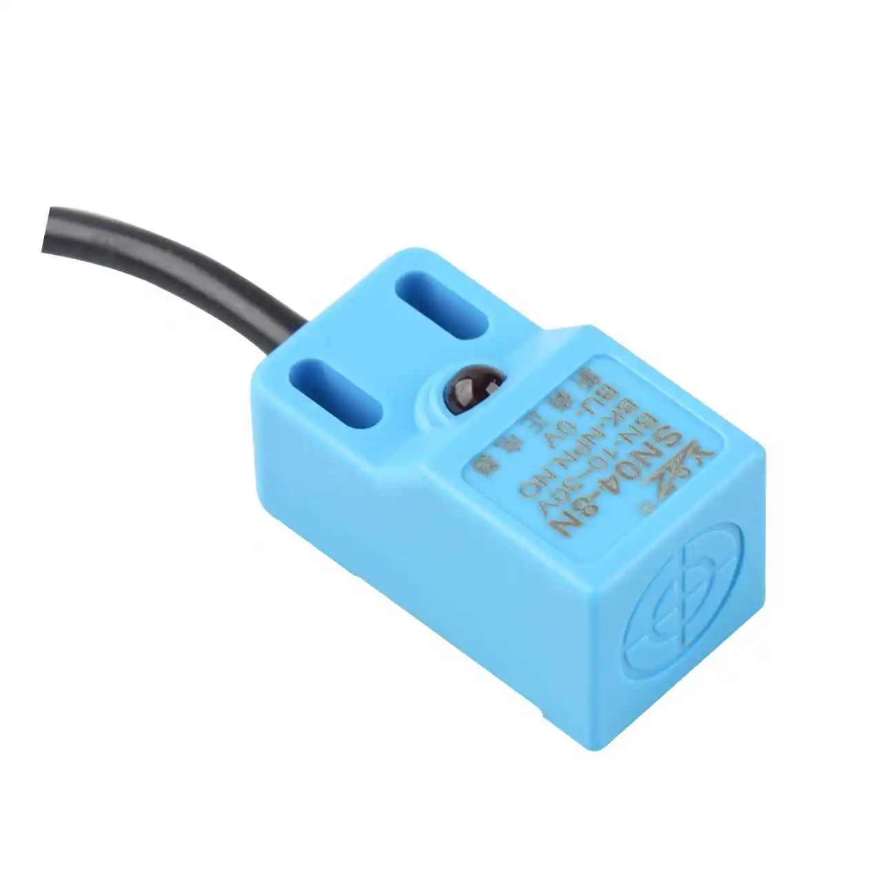
Best starting point for nearby metal
Inductive sensing is useful when a metal part passes close to the active face and the installation should not depend on a clean optical path.
- Detects metal rather than general material color
- Compact threaded and rectangular mounting formats
- Target alloy, size and nearby metal affect usable distance
- Flush or non-flush mounting rules must be followed

Best general-purpose optical family
Photoelectric sensors can detect many materials and provide several optical arrangements. Access, target optics and background determine the correct mode.
- Through-beam for a clear interruption across two sides
- Retro-reflective when a reflector can be installed opposite
- Diffuse or BGS when all wiring must remain on one side
- Transparent, shiny and very dark parts need sample testing
Best starting point for a small sensing head
A fiber unit carries light between a compact head and a separate amplifier. It can place the detection point in a narrow fixture or away from electronics.
- Small heads, sleeves and focused spot options
- Useful around tiny parts and constrained mechanisms
- Amplifier remains accessible for setup and diagnostics
- Head type, bend limits, response and target contrast still matter
Do not compare only nominal sensing distance. For inductive proximity sensors, the reference target, target material, target size and surrounding metal influence actual operation.1 For photoelectric and fiber optic sensors, minimum detectable object and sensing range depend on the exact optical unit, target, setup and test condition.3
Optical Arrangement
"Photoelectric" is a family, not one detection behavior.
Mounting access and the no-part background often eliminate options before distance is considered. Through-beam, retro-reflective, diffuse and background-suppression sensors solve different geometry problems.2
Through-beam
Use whenA transmitter and receiver can face each other and the part reliably interrupts the beam.
ValidateSmallest target versus beam size, clear-object behavior, alignment, vibration and cable access on both sides.
Retro-reflective
Use whenSensor wiring must stay on one side but a reflector can be mounted opposite the sensing point.
ValidateReflector size and angle, shiny target reflections, clear target attenuation and contamination over the full optical path.
Diffuse
Use whenOnly one mounting side is available and the target can return enough light to the receiver.
ValidateDarkest, glossiest and most tilted approved surface, plus the brightest background in the no-part condition.
Background suppression
Use whenA defined target zone must be separated from a conveyor, fixture or machine panel behind it.
ValidateTarget distance variation, target shape, background distance, angled surfaces and the exact teach or adjustment procedure.
Slot or groove
Use whenA small guided tab, edge, label, pin or component can pass through a fixed U-shaped sensing gap.
ValidateMechanical clearance, repeatable path, slot width, minimum feature and debris accumulation inside the slot.
Difficult Targets
Choose around the weakest contrast, not the easiest sample.
A target category such as "plastic" is not enough. Clear PET, matte black plastic and glossy white plastic create different optical conditions even when their dimensions are identical.
Glass, PET and clear film
Test a dedicated transparent-object optical mode, a suitable through-beam or retro-reflective arrangement, capacitive sensing or another technology according to wall thickness, shape and access. Test empty, full and wet conditions when relevant.
Polished metal and foil
Specular reflections can appear or disappear with a small angle change. Through-beam interruption, polarized retro-reflective sensing, controlled beam geometry or inductive sensing may provide a more repeatable distinction.
Black rubber, foam and dark resin
Diffuse return may be weak. Check through-beam, retro-reflective, BGS or a fiber head selected for the required contrast, and validate the darkest approved batch at maximum target distance.
Pins, leads, clips and miniature parts
The relevant value is the model-specific minimum detectable feature in the real geometry, not a universal object-size claim. A focused fiber spot, slot sensor or light array may control the optical zone more precisely.
Tilted, bouncing or irregular parts
First stabilize presentation with guides or a nest. Then widen the valid detection zone without exposing the background. An array can be better than a single beam when path variation cannot be removed.
Multiple approved colors and materials
Use the sensing principle least dependent on the changing property. For example, beam interruption can be less color-dependent than diffuse reflection, while an inductive sensor can ignore non-metal color entirely.
Timing Check
Make sure the part remains visible long enough for the complete signal chain.
A sensor LED can flash while the PLC misses the event. Estimate the shortest part dwell at the sensing point, then compare it with sensor response, input filtering and program timing. Use exact device documentation for final validation.
Part detection window estimator
Enter the shortest feature along travel and the fastest operating condition.
The target window is longer than the entered delay allowance.
The entered timing chain consumes about 40% of the part-presence interval. Confirm both ON and OFF behavior on the real PLC input.
Planning aid only. The calculation uses part length / speed for dwell and one entered scan interval as an allowance. Beam geometry, edge position, output pulse behavior, jitter, network update and program execution can change the real result.
Part geometry
The actual visible feature enters and leaves the sensing zone.
Optical or field response
The sensor creates enough internal contrast to change state.
Sensor output
The selected output switches after its specified response time.
PLC input
Wiring polarity, threshold and input filtering accept the pulse.
Machine logic
The program samples the correct state and applies the intended action.
Installation Controls
Design the bracket, background and PLC input with the sensor.
Many unstable applications are not solved by changing only the sensor body. The mounting structure, cable route, target presentation and controller configuration are part of the detection system.

Create a rigid reference
Mount the sensor and any reflector or receiver to structure that does not move relative to the target path. Avoid thin sheet, long unsupported brackets and impact-prone locations.
Separate target and no-target states
Measure the nearest and farthest approved part position and the closest background. Set the sensing zone so normal variation does not consume the full usable margin.
Protect the sensing face
Consider chips, oil, washdown, dust, condensation, labels and operator contact. A guard should protect the sensor without creating a new reflective surface or trapping debris.
Control optical interference
Check adjacent sensors, direct machine lighting, sunlight, reflective guards and side-by-side installation. Use the model's interference-prevention and spacing guidance where provided.
Match the electrical interface
Confirm supply voltage, PNP or NPN output, normally open or normally closed behavior, load current, connector pinout and the PLC input common before energizing.
Preserve the final setup
Record model, bracket position, teach value, sensitivity, indicator state, input address, filter, logic meaning and approved samples so maintenance can reproduce the result.
Escalate The Method
Know when one point sensor is not enough.
A single output can answer one repeatable yes-or-no question. Add spatial information when approved parts vary too much or when the control decision depends on identity, orientation or several features.
Use two point sensors
Confirm presence and seating, or distinguish correct orientation through two independent target features.
Use a light array or grid
Cover a wider detection height when small parts move through several valid lanes or positions.
Use multiple beams
Check part height, an exposed profile, several pins or a sequence that one beam cannot resolve.
Use machine vision
Choose vision when the decision depends on shape, print, color pattern, orientation, assembly detail or classification.
Commissioning Plan
Validate the complete decision with real production extremes.
Bench switching proves only that one sample can be detected once. A production validation should challenge approved variation, no-part backgrounds, maximum speed and abnormal machine states while observing both the sensor and PLC.
Build the challenge set
Include the smallest, farthest, darkest, clearest, glossiest, most tilted and most contaminated approved parts where relevant. Add known wrong parts and an empty fixture.
Run realistic conditions
Use the final bracket, guard, cable, background and controller. Run maximum speed, normal vibration, machine lighting and adjacent sensors or equipment.
Observe every layer
Compare the physical part, sensor indicator, sensor output, PLC input and final machine decision. A mismatch identifies the layer that needs correction.
Test start, stop and fault states
Stop with the part at the switching edge, restart, remove the part, create a jam and disconnect the sensor where safe to confirm the intended logic response.
Challenge maintenance conditions
Evaluate a realistically dirty lens or face, acceptable bracket tolerance and replacement setup. Define the cleaning and inspection trigger before the signal becomes unreliable.
Save acceptance evidence
Document tested samples, distances, settings, speed, input configuration, result and approver. Keep the baseline with the machine documentation and spare part record.
Installed Cost
Compare the complete detection point, not only the sensor price.
A less expensive sensor can create higher installation and maintenance cost if it requires frequent realignment, difficult reflector access, extra guarding or repeated setup for product changes.
Hardware
Sensor, fiber amplifier, receiver, reflector, bracket, connector, cable, guard and any additional PLC input.
Integration
Mechanical design, wiring access, alignment, teach procedure, program changes and acceptance testing.
Operation
Cleaning interval, product changeover, nuisance stops, false accepts, diagnostic visibility and operator intervention.
Lifecycle
Spare standardization, replacement repeatability, documentation, supplier support and the cost of an undetected missing part.
Application Review
Send six facts for a useful sensor recommendation.
A part photo alone rarely shows the hardest condition. Include dimensions, target variation, mounting access, environment and PLC interface so the proposed model can be checked against the real detection task.
Request an XSZ recommendationMaterial and finish
Metal alloy, plastic color, transparency, gloss, texture and the smallest approved part or feature.
Distance and tolerance
Nearest and farthest target position, travel direction, tilt, lateral movement and background distance.
Available mounting
One-side or two-side access, reflector allowance, head space, bracket surface and cable exit direction.
Speed and required proof
Fastest speed, shortest dwell and whether the machine needs presence, position, orientation or completeness.
Contamination and exposure
Oil, dust, chips, water, washdown, temperature, vibration, ambient light and nearby sensors.
Controller interface
Supply voltage, PNP or NPN, NO or NC, connector preference, PLC input and any response-time requirement.
Frequently Asked Questions
Sensor for part presence detection FAQ
Short answers to common engineering and purchasing questions before sample validation.
What is the best sensor for part presence detection?
There is no universal best type. Start with inductive proximity for a nearby metal target, photoelectric for general materials and a usable optical path, or fiber optic when the sensing head must be very small or placed in a tight fixture. The final choice depends on the worst target, mounting access, background, environment, speed and PLC interface.
Can a proximity sensor detect plastic parts?
An inductive proximity sensor detects metal and does not directly detect ordinary plastic. A capacitive proximity sensor may detect some plastics, but moisture, buildup, wall thickness and nearby material can affect stability. Photoelectric or fiber optic sensing is often considered when the plastic target presents usable optical contrast.
Which photoelectric mode is least affected by target color?
Through-beam detection is generally less dependent on reflected target color because the target interrupts a beam between transmitter and receiver. It is not automatically correct for every transparent or very small part, so beam size, target transmission, alignment and the exact model still need to be tested.
Is a fiber optic sensor better for very small parts?
It can be a strong starting point because small heads, sleeves, focused spots and slot-style fiber units can create a compact sensing point. "Fiber optic" alone does not guarantee a particular minimum object size. Select the exact head and amplifier, then test the smallest part across its full position tolerance.
How fast must a part presence sensor respond?
Calculate the shortest time the required part feature remains in the sensing zone. That interval must support the sensor response, output behavior, PLC input filter, controller update and program logic with validated margin. Use the exact sensor and PLC documentation rather than a technology-wide response-time assumption.
Can one sensor check both presence and orientation?
Yes, but only when correct and incorrect orientation create a repeatable difference at one sensing point. If several orientations can produce the same signal, use two point sensors, a light array or machine vision to collect enough spatial information.
Do PNP, NPN, NO and NC affect detection performance?
They do not change the physical sensing principle, but they determine whether the output works correctly with the controller and how the normal logic state is interpreted. Confirm PNP or NPN compatibility, NO or NC behavior, connector pinout, voltage and PLC input common before commissioning.
Can a standard part presence sensor be used for machine safety?
No. A standard industrial sensor used for part detection is not a safety-rated personnel protective device. Hazardous machine access requires a safety function designed and validated with suitable safety-rated components and applicable risk-reduction requirements.
Source Notes
Technical references and image credits
Technical references
- OMRON, Proximity Sensor Safety Precautions - target material and size, surrounding metal, installation leeway and non-safety use.
- OMRON, Photoelectric Sensors Introduction - through-beam, retro-reflective, diffuse and distance-settable arrangements and selection considerations.
- OMRON, Photoelectric Sensor Further Information - model and test-condition dependence of minimum detectable objects.
- OMRON, Fiber Sensors Introduction - compact fiber heads, narrow-space installation and separate fiber unit and amplifier architecture.
- KEYENCE, Fiber Sensor Classification - small-spot, focused-beam, narrow-space and specialized target options.
- Banner Engineering, Part Detection for Error Proofing - part-presence detection as an error-proofing application.
Turn the part, distance and PLC requirement into a testable sensor choice.
Send XSZ the target material, smallest feature, position tolerance, mounting access, environment, maximum speed and required output. We can help narrow the sensing principle and the sample conditions to validate before release.