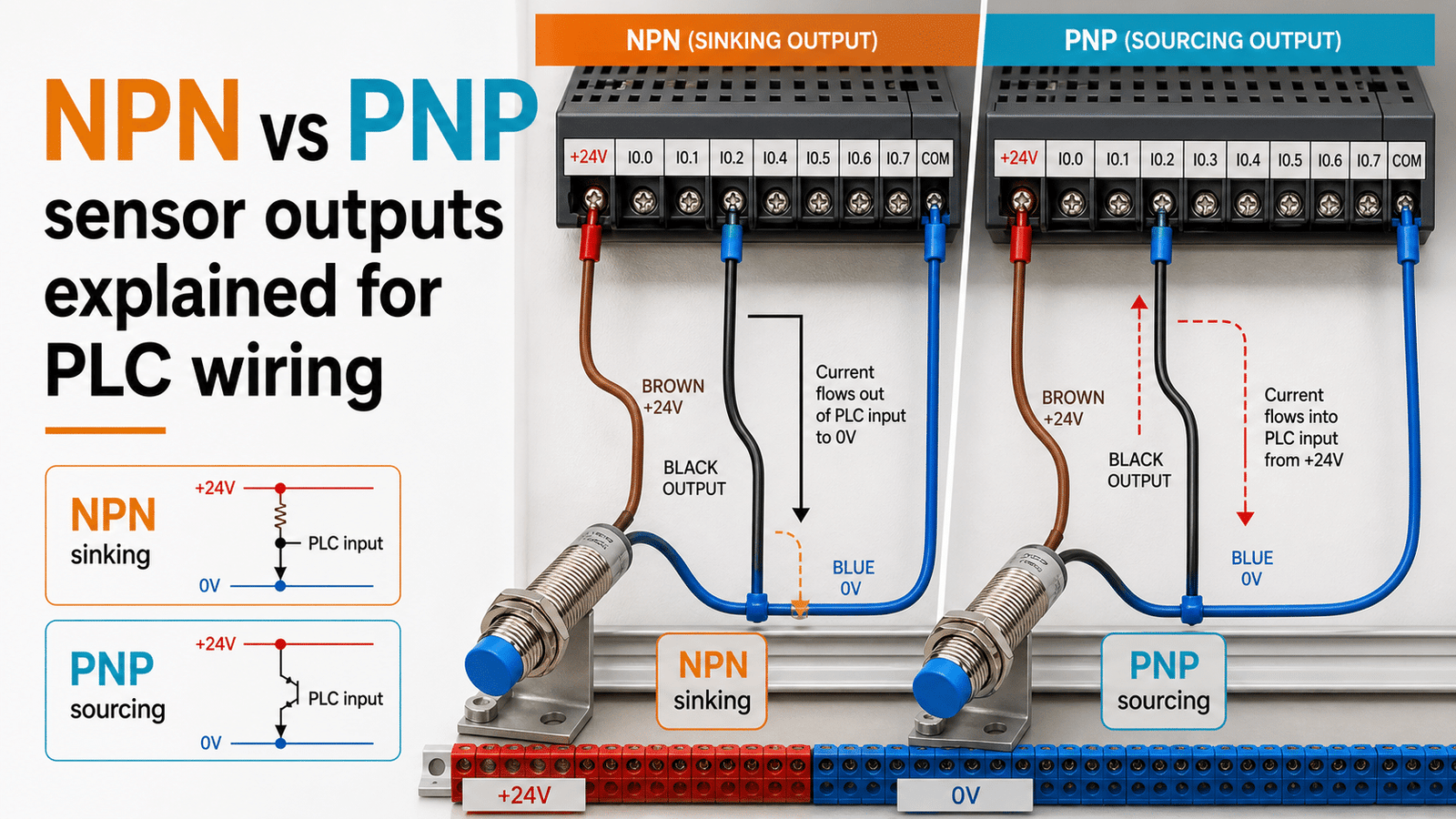
In an NPN vs PNP sensor comparison, the key difference is which side of the circuit switches: a PNP sensor switches the positive side (sourcing), delivering +24 V[1] to the load when it turns on, while an NPN sensor switches the negative side (sinking), pulling the load to 0 V. Both use three wires—brown (+24 V), blue (0 V), and black (signal). This distinction determines wiring: PNP sensors pair with sinking PLC inputs, and NPN sensors pair with sourcing inputs.
What is the electrical difference between the two? How do you go about wiring each type to a PLC input? Which one works with sinking versus sourcing input cards? And which should you pick for a new build in 2026?
Quick Takeaways
- PNP sensors source +24 V to the load; NPN sensors sink to 0 V.
- Pair PNP outputs with sinking PLC inputs; NPN with sourcing inputs.
- All 3-wire sensors use brown (+24V[2]), blue (0V), black (signal) wires.
- Wrong output type leaves inputs dead or permanently on.
- Choose PNP for new 2026 builds; Europe standardizes on it.
What’s the difference between an NPN and a PNP sensor output?
An NPN sensor switches the negative side of the circuit, the ground side, while a PNP sensor switches the positive side instead. Banner Engineering describes PNP outputs as sourcing, meaning they deliver positive voltage to the load when the sensor turns on, and that voltage is usually +24 V[3] to match the supply. NPN outputs sink current the other way, pulling the signal line down to 0 V. This one difference essentially decides how you wire the sensor to a PLC.
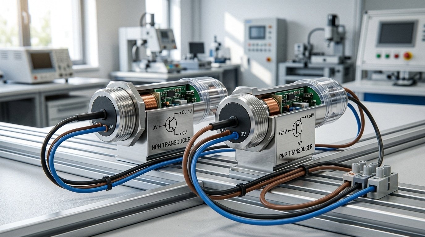
The thing that actually changes is the output transistor. Inside every 3-wire sensor there is a switching transistor that conducts when the sensor spots a target. In an NPN device, that transistor connects the output wire straight to ground, which is 0 V, so current flows Into the sensor, and that is why we call it “sinking.” In a PNP device, the transistor connects the output to +24 V, pushing current Out toward the load, which is where the term “sourcing” comes from.
That opposite current direction is really the reason the two types can’t be swapped around freely. A 2024 Control.com article confirmed that PNP sensors, the sourcing kind, must pair with sinking input modules, while NPN sensors, the sinking kind, need sourcing input modules. Mix them up and the input never sees the signal, so the machine reads a permanent “off” even when the target is sitting right in front of the face.
Here is one trap that catches beginners. The NPN vs PNP sensor choice has nothing to do with normally open or normally closed, and both types can be either one. You pick NPN or PNP based on your PLC’s input card, not on the switching logic itself.
What do sinking and sourcing mean in current flow terms?
Sinking means pulling current toward ground; sourcing means pushing current out from the supply. An NPN sensor sinks current from the PLC input, while a PNP sensor sources current into it. Industry documentation from 2024 confirms that PNP “pulls up” (sources) and NPN “pulls down” (sinks), so the two sensor types move current in opposite directions through the same load. Conventional current flows from plus (+24 V) to minus (0 V), and tracing that path is the key to the whole NPN vs PNP sensor debate.
How does an NPN sensor sink current from the PLC?
An NPN sensor sinks current: it gives the PLC input a path to ground. When the sensor switches on, current starts at the PLC’s +24 V rail, flows through the internal input resistor (usually around 3 kΩ, drawing about 7 mA), out the input terminal, into the sensor’s output wire, and down through the NPN transistor to 0 V. The sensor acts like a switch to ground.
How does a PNP sensor source current into the PLC?
A PNP sensor sources current: it delivers +24 V to the PLC input. Control.com’s 2024 guide confirms PNP outputs provide positive voltage and pair with sinking input modules. Current leaves the sensor’s supply, passes through the PNP transistor, out the output wire into the PLC terminal, through the input resistor, and returns to 0 V[4] inside the card.
Practical tip: trace the current arrow before wiring. If the ground path runs through the sensor, it’s NPN.

Why does the PLC input card type decide which sensor you need?
The polarity of the input card is what decides which sensor you need, not the sensor deciding for you. If you have a sinking input card, it needs a PNP sensor, which is the type that sources current, and if you have a sourcing input card, it needs an NPN sensor, which is the type that sinks current. A 2024 Control.com technical article backs up this pairing, explaining that the card and the sensor have to push current in opposite directions so the electrical loop can close. Essentially one side has to give current out and the other side has to take it in.
If both of them try to sink current, or both try to source it, then nothing flows at all and the input point simply never switches on.
How do you read the common terminal to know which card you’ve?
Take a look at the shared terminal on the input card, the one labeled “common.” If that common terminal connects to +V (24 V DC), then you have a sinking card, so you should pair it with a PNP sensor. If instead the common connects to 0 V (ground), then you have a sourcing card, and that one wants an NPN sensor.
- Common = +24 V: this is a sinking input card, so it needs a PNP sensor
- Common = 0 V: this is a sourcing input card, so it needs an NPN sensor
This one simple check settles most NPN vs PNP sensor debates before you ever touch a wire. You should never trust the color of the label or whatever a supplier hands you as their default option. Instead, open up the terminal map in the PLC manual and follow where the input group’s common actually lands. When you wire a matched pair together, the input point reads correctly on the very first try, with no diode tricks and no interface relays needed.
How do you wire an NPN sensor versus a PNP sensor to a PLC?
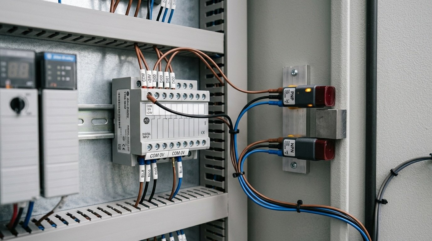
Both sensor types use the same three wires, brown (+24 V), blue (0 V[5]), and black (signal), though the black signal wire lands on different terminals and the PLC common (COM) reverses between them. An NPN signal goes to a sourcing input card whose COM ties to +24 V, while a PNP signal goes to a sinking input card whose COM ties to 0 V. As Control.com documented in 2024, PNP (sourcing) sensors pair with sinking modules, and NPN (sinking) sensors pair with sourcing modules.
How do you wire an NPN sensor?
You connect brown to +24 V, blue to 0 V, and black to the input terminal. When the sensor turns on, its internal NPN transistor pulls the black wire down to 0 V. Current then flows out of the input card, through the sensor, and to ground. And because the load side sinks to ground, the input card’s COM has to reference +24 V.
How do you wire a PNP sensor?
You keep the same power connections, brown to +24 V[6] and blue to 0 V. The black wire still goes to the input terminal, but now the switched-on PNP transistor pushes +24 V out to that terminal. Current flows from the sensor into the input, then out through the card’s COM to 0 V. In this case the card’s COM has to reference 0 V.
| Terminal | NPN sensor | PNP sensor |
|---|---|---|
| Brown wire | +24 V | +24 V[7] |
| Blue wire | 0 V | 0 V |
| Black (signal) | Input terminal | Input terminal |
| Input card COM | +24 V | 0 V |
A useful field tip is to label the COM jumper before you energize anything. Swapping COM polarity is generally the single fastest way to make a correctly wired sensor read as permanently on or completely dead.

Why is PNP standard in Europe but NPN common in Japan and Asia?
PNP dominates Europe because IEC-based machinery standards favor positive-switching (sourcing) outputs for safety, while Japan and much of Asia historically built automation around NPN (sinking) outputs to match domestic PLC input cards. This split means a spare sensor bought for a German line often won’t drop into a Japanese-built machine without rewiring or a converter.
⚠️ Common mistake: Wiring a PNP (sourcing) sensor to a sourcing PLC input card, leaving the input permanently dead or floating. This happens because both the sensor and input try to supply +24 V, so no current path to 0 V[8] ever forms. The fix: pair PNP outputs with sinking input cards, and NPN outputs with sourcing cards—match the sensor’s switched side to the input’s opposite reference.
Why did European designs settle on PNP?
European safety practice leans on positive switching. A PNP sensor delivers +24 V to the load when it triggers, so a broken signal wire reads as “off” instead of a false “on.” This fits the fault-detection logic in IEC 61131 machinery standards. Balluff’s 2024 sensing guide confirms PNP outputs switch the positive side of the circuit, which German and Italian OEMs treat as the default.
Why does Asian automation lean toward NPN?
Japanese controls historically used sinking input cards, so NPN sensors became the plant standard. Machines built in Japan, South Korea, and China often ship with NPN throughout. Retrofitting one region’s spare into the other’s line means the NPN vs PNP sensor mismatch will simply fail to register, the input polarity won’t match.
How does this affect spare-part sourcing?
- Stock both output types: mixed-origin plants running German and Japanese machines need separate sensor bins to avoid substitution errors.
- Check the input card first: buy the output type your existing PLC card demands, not the type printed on the old sensor label.
- Use NPN/PNP-selectable sensors: many current models offer a switchable output, cutting your spare inventory in half.
How do NPN and PNP sensors behave during wire faults and short circuits?
A short-to-ground on an NPN signal wire mimics an active signal, because an NPN output already pulls the input to 0 V when it switches on. The PLC reads “true” even with the sensor unplugged. A PNP short-to-ground reads “false” instead, since PNP switches the positive side. This single behavior gap is why PNP is the fail-safe default in most machine-safety designs.
Why does a shorted NPN output create a dangerous false signal?
An NPN sensor connects its signal wire to ground (0 V) when active, the same electrical state a chafed wire touching the machine frame produces. The PLC can’t tell a real detection from a fault. In a guard-door circuit, that means the controller believes the door is closed when the cable is actually damaged. The Digi-Key TechForum in 2024 confirmed that NPN outputs “pull down” toward ground, which is exactly why the failure looks like a valid input.
Why is PNP safer for fail-safe wiring?
With PNP, a broken wire or short-to-ground removes the positive signal, so the input drops to “false”, a de-energized, safe state. This aligns with the de-energize-to-trip principle in IEC 61508 functional safety. Design engineers pick PNP so that any fault fails toward the stopped condition. In an NPN vs PNP sensor choice for safety loops, this fault behavior, not price, usually decides it.
NPN vs PNP sensor comparison — which should you choose?
Choose the sensor that matches your PLC input card, not the other way around. A sourcing input card needs an NPN (sinking) sensor; a sinking input card needs a PNP (sourcing) sensor. In a 2024 Control.com technical article, engineers confirmed that PNP sensors pair with sinking modules and NPN sensors pair with sourcing modules. Get this mismatch wrong and the input simply never triggers.
Card polarity isn’t the only factor, though, regional standards, legacy equipment on the same line, and safety needs all pull the decision. Use the matrix below to lock your choice fast.
| If your situation is… | Then pick… | Watch out for |
|---|---|---|
| Sourcing input card (common) | NPN sensor | Short-to-ground faults mimic a signal |
| Sinking input card | PNP sensor | Verify card is truly sinking, not selectable |
| New European machine (IEC) | PNP sensor | Spare parts and support skew PNP |
| Matching legacy Japanese line | NPN sensor | Don’t mix polarities on one card |
| Safety-rated input needed | PNP sensor | Ground faults default to off-state |
The safety exception matters most. PNP wiring fails to a safe off-state when a signal wire shorts to ground, which is why safety inputs favor it. Skip NPN on any circuit tied to guarding or e-stop logic. When stock and standards conflict, let the card decide first, then buy the sensor to suit.
What are the most common NPN and PNP miswiring mistakes?
The most common miswiring mistake is pairing a sensor with the wrong input card polarity. An NPN (sinking) sensor connects the output to ground when active, so it needs a sourcing input card. Wire that same NPN sensor into a sinking card and you get zero signal, the two devices both try to pull current the same direction, and nothing latches. A quick meter check confirms it in under a minute.
Why does an NPN sensor on a sinking card give no signal?
Because both the sensor and the card sink current, there’s no path to complete the loop. The 2024 industry rule is clear: NPN sinking sensors need sourcing input modules, and PNP sourcing sensors need sinking modules. Symptom: input stays OFF no matter what you place in front of the sensor. Meter check: set your multimeter to DC volts, probe the black signal wire against 0 V, an active NPN output should read near 0 V; a working PNP output reads about +24 V.
What happens if you tie the wrong common terminal?
Symptom: inputs read inverted or stay stuck ON. Root cause: the input card common bus is tied to +24 V[9] when it should sit at 0 V (or vice versa). Meter check: measure the common terminal against 0 V, a sourcing card common should read +24 V, a sinking card common should read 0 V.
Voltage mismatch is the third trap. A 12 V sensor feeding a 24 V[10] card may never cross the logic threshold, giving flickering or dead inputs. Match the NPN vs PNP sensor output voltage to the card’s rated input range before you power up.
Frequently asked questions about NPN and PNP sensors
Yes, you can convert NPN to PNP with an interposing relay, but it adds cost and a failure point. A relay coil driven by the sensor breaks the polarity dependence, giving you a clean dry contact that any input card accepts. Most engineers skip this and just order the correct sensor instead.
Are two-wire sensors NPN or PNP?
Two-wire sensors are neither in the strict sense, they carry load current through the same pair of wires used for power. Because they wire in series with the load, a single two-wire model works on both sinking and sourcing inputs. The trade-off is leakage current, often 0.5 to 2.5 mA, which can falsely trigger high-impedance PLC inputs.
Which is safer, NPN or PNP?
PNP is generally safer in modern machinery. A short-to-ground on a PNP signal wire produces 0 V, reading as OFF, a fail-safe state. On NPN, the same fault mimics an active signal. This logic is why IEC-aligned European designs default to PNP.
How do you identify an unmarked sensor with a multimeter?
Power the sensor with 24 V, then measure the black signal wire against ground. If the signal reads near +24 V when the target is present, it’s PNP (sourcing); if it reads near 0 V, it is NPN (sinking). In 2024, Balluff confirmed NPN switches the ground side while PNP switches the positive side, the exact behavior your meter reveals during an NPN vs PNP sensor check.
Choosing the right sensor output for reliable PLC wiring
Verify your PLC input card polarity before you order any sensor. In the 2024 Control.com breakdown, PNP (sourcing) sensors must pair with sinking input modules, while NPN (sinking) sensors must pair with sourcing modules. The card decides the choice, not the sensor. Get this backward and the input never reads a signal, no matter how the sensor is wired.
The debate over NPN vs PNP sensor selection usually skips the one fact that matters: your existing hardware already picked for you. Read the card datasheet and look for “sinking input” or “sourcing input” printed near the terminal diagram. That single line settles the order.
What should your pre-order checklist include?
Run these four checks before purchasing, in order:
- Card polarity: confirm sinking vs sourcing from the input module datasheet, not the sensor page.
- Regional standard: IEC-based European machines expect PNP; older Japanese and Asian lines often run NPN.
- Contact type: pick normally open (NO) or normally closed (NC) separately — polarity and contact type are independent choices.
- Cable color match: brown to +24 V, blue to 0 V, black to the correct signal terminal.
Order in bulk only after one sample tests clean on the live card. A five-minute polarity check saves the cost of restocking a full tray of wrong-polarity sensors, a mistake that stalls initial startup by days on multi-station lines. Match the card, match the region, then buy.
See also
PNP sensor wiring diagram with simple step by step guide
Which analog proximity sensor output is better, 0–10 V or 4–20 mA
2 wire vs 3 wire sensor differences that actually matter
Why tiny metal parts need a different ring sensor




