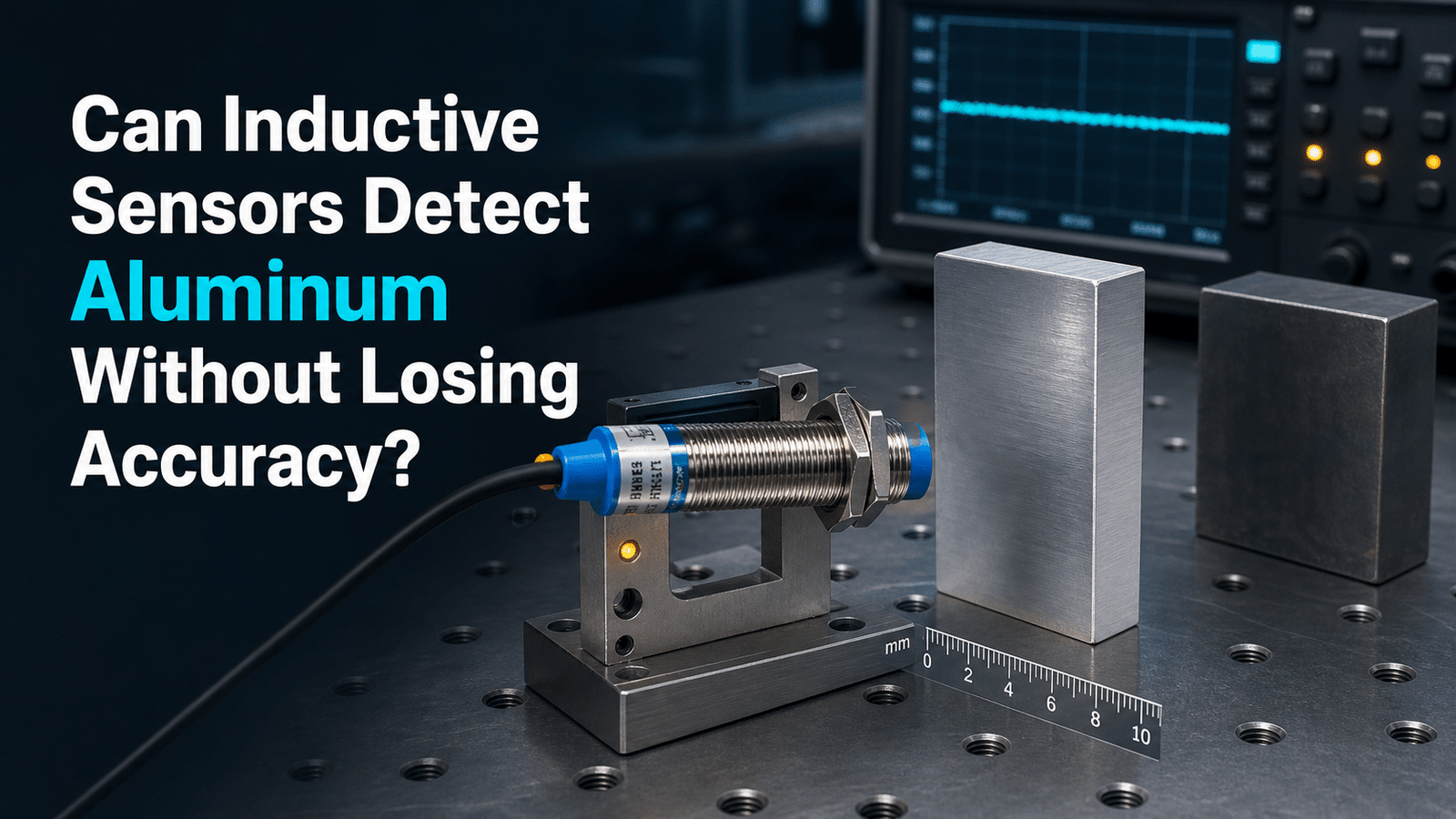
An inductive sensor detects aluminum reliably, but only at a shorter range than it reads steel. Testing shows the sensing distance drops by roughly 40%[1], with a correction factor near 0.30–0.45 for aluminum compared to 1.0 for Fe360 steel, per Baumer sensor specifications (2025). Eddy currents in aluminum produce a weaker signal, so you need to mount the sensor 30–approximately 45% closer or choose a Factor 1 sensor, which reads aluminum, steel, and brass at equal distance.
So yes, the sensor still triggers reliably. You just have to shorten the mounting gap and pick the right type of sensor for the job.
This guide answers the questions that engineers actually ask when they run into this. Why does aluminum weaken the signal in the first place? How do you calculate the corrected sensing range once you account for the metal? Which sensor variants, whether standard or the factor 1 kind, help close that gap? And how do you keep the readings consistent and repeatable when the target metal changes from one material to another?
Quick Takeaways
- Aluminum cuts standard inductive sensing range by about 40% versus steel.
- Correction factor for aluminum sits near 0.30–0.45, with steel at 1.0.
- Factor 1 sensors detect aluminum, steel, and brass at equal distance.
- Mount sensors 30–approximately 45% closer on aluminum to keep switching repeatable.
- Choose Factor 1 sensors when target metals change frequently across your line.
Can inductive sensors detect aluminum?
Yes, it does. A standard inductive sensor detects aluminum reliably, but only at a shorter range. The sensing distance actually drops to roughly 0.35 to 0.45 of the rated distance (Sn) that gets measured on steel, per Baumer’s 2025 correction data. That one number should really guide every mounting decision you end up making.
The drop happens because of how the sensor actually works. An inductive sensor puts out a high-frequency electromagnetic field, basically an invisible magnetic zone, right at its face. When metal moves into that field, tiny circulating currents called eddy currents form inside the target, pull energy away from the field, and the sensor reads that loss as a “detection.” Aluminum has lower magnetic permeability than iron, meaning it holds onto a magnetic field less easily, so it disturbs the field far less. Less disturbance means the target has to sit much closer before anything triggers.
The math here is unforgiving. Take a sensor rated at 12 mm[2] on Fe360 steel. Once you apply a correction factor somewhere near 0.4, your usable range on aluminum shrinks to about 4.8 to 5 mm. Design your gap for the full 12 mm and the sensor essentially never sees the aluminum part at all.
Practical rule: always mount aluminum targets at least 30 to approximately 40% closer than you would for steel, and then confirm it with a live switching test. If your mechanical layout just can’t get that close, you need a Factor 1 sensor instead, which is a design that detects all metals at nearly the same range. That option gets a full breakdown later on in this guide.
How do inductive sensors detect conductive non-ferrous metals like aluminum?
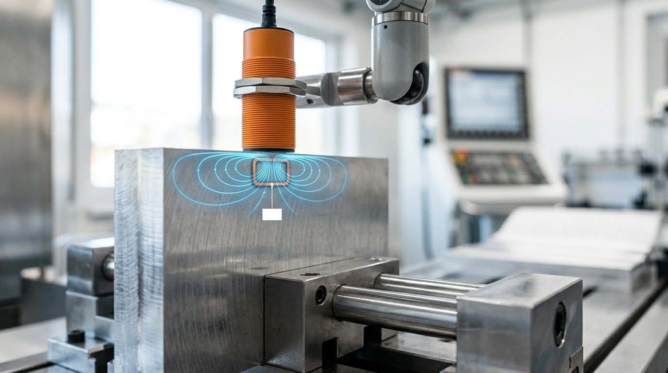
An inductive sensor detects aluminum through eddy-current damping alone, without any magnetic pull, which is why detection works but stays weak. The oscillator coil creates a high-frequency field. When aluminum enters it, that field induces swirling currents in the metal, draining energy from the oscillator and triggering the output, but at up to 60% less range than steel, as Wikipedia’s inductive sensor overview confirms.
The physics is straightforward: the coil oscillates at a fixed frequency, often 100 kHz to 1 MHz. Any nearby conductor gets hit by these fields and fights back with induced eddy currents, which burn energy so the oscillation shrinks. The sensor reads that drop and switches. Steel and aluminum play very different games here.
- Steel (ferromagnetic): gets a double effect — magnetic field concentration plus eddy currents. Both damp the coil hard, so the signal is strong at long range.
- Aluminum (non-magnetic, highly conductive): gives no magnetic boost. Only eddy currents respond. Because aluminum’s conductivity (about 37 MS/m) is high, its eddy currents flow near the surface and reflect much of the field back, weakening the damping effect.
That eddy-only, magnetic-free reaction is exactly why range collapses. The sensor still knows aluminum is there, it just needs the target far closer. Section 3 puts hard numbers on that loss.
How much sensing distance is lost for aluminum versus steel?
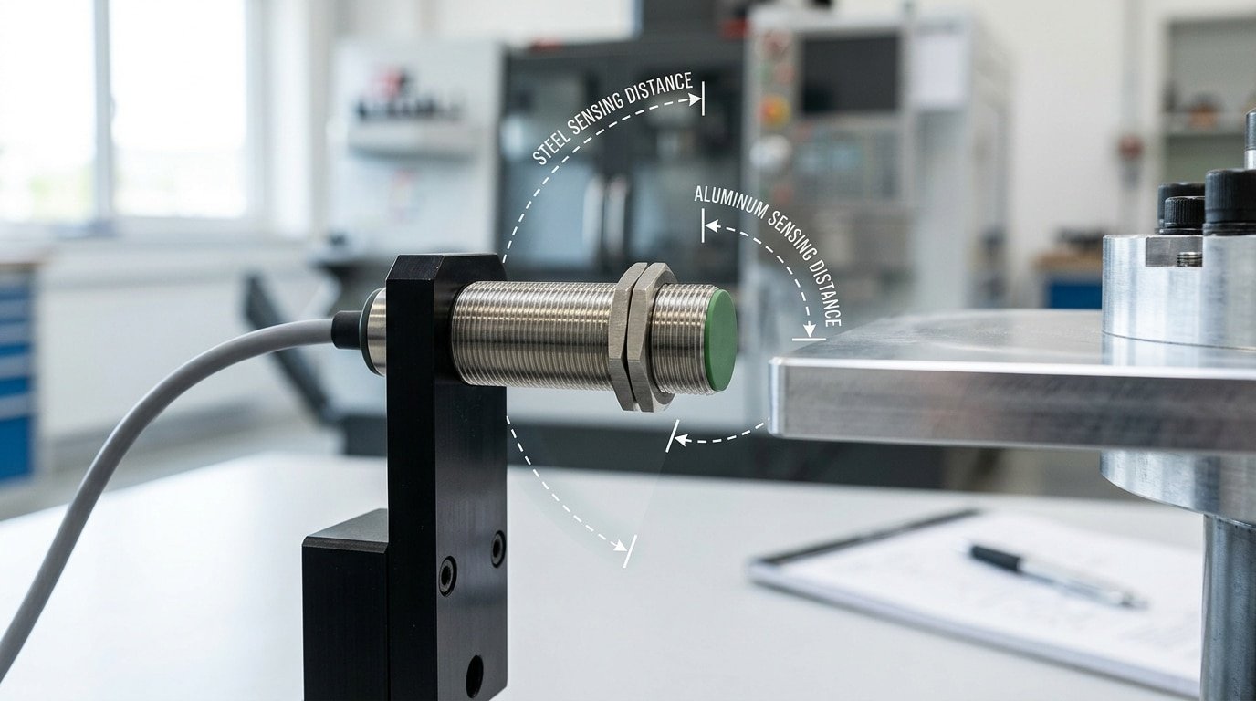
Aluminum cuts effective range to roughly 35,45%[3] of the steel value. When an inductive sensor detects aluminum, industry correction tables assign it a factor near 0.4 against mild steel’s baseline of 1.0, meaning Baumer’s data shows about a 40% shorter operating distance on non-ferrous targets.
The math is simple: multiply the sensor’s rated sensing distance (Sn) by the material’s correction factor to get real range. A sensor rated 12 mm on steel gives roughly 4.8,5 mm on aluminum at factor 0.4, according to RealPars.
| Target metal | Correction factor | Real range from Sn = 12 mm |
|---|---|---|
| Mild steel (Fe360) | 1.0 | 12 mm |
| Stainless steel | 0.65–0.85 | 7.8–10.2 mm |
| Brass | 0.35–0.50 | 4.2–6.0 mm[4] |
| Aluminum | 0.35–0.45 | 4.2–5.4 mm |
| Copper | 0.30–0.40 | 3.6–4.8 mm |
Practical rule: never design a mounting gap right at the calculated maximum. Set your working distance at 70,80% of the corrected value. If aluminum yields 5 mm, mount the target at 3.5,4 mm. This leaves margin for temperature drift and vibration, which can shift trip points by tenths of a millimeter over a shift.

Why does skin effect and target thickness change aluminum detection?
Skin effect and target thickness both control aluminum detection because eddy currents, which are the small looping currents the sensor induces in metal, tend to crowd into a thin surface layer that gets set by the sensor’s oscillation frequency. When aluminum foil is thinner than this layer, the sensor can’t build up enough current to trigger, so an inductive sensor detects aluminum only above a certain minimum thickness.
What’s skin effect and why does it matter here?
Skin effect pushes the eddy currents toward the surface of the target as the frequency rises. At a typical sensor oscillation frequency of 100,800 kHz[5], the skin depth in aluminum sits somewhere near 0.08,0.26 mm. Below that depth, the current density drops off fast, and that’s really why aluminum already cuts the sensing range so hard, reducing the range by up to about 60% compared to ferrous metals.
How thin is too thin for reliable detection?
Foil below roughly 0.1 mm will often fail to switch a standard sensor at its rated distance. Here’s some practical guidance to work with:
- Below 0.05 mm foil: unreliable, since the eddy currents are just too weak; use capacitive or optical instead.
- 0.1–0.2 mm sheet: detectable at a reduced range, so test it at your actual gap.
- Above 1 mm[6] plate: full eddy-current response, and at that point thickness no longer limits detection.
As a rule of thumb, the target thickness should exceed one skin depth, and ideally two. Thicker aluminum doesn’t extend the range any further, because once the eddy currents saturate that surface layer, the extra metal essentially adds nothing.
What are Factor 1 all-metal inductive sensors and do they detect aluminum at full range?
Factor 1 sensors are all-metal inductive sensors that hold a correction factor of 1.0 across steel, stainless steel, brass, copper, and aluminum. So yes, this type of inductive sensor detects aluminum at its full rated distance. A 12 mm sensor gives you 12 mm on aluminum, not the roughly 5 mm a standard model manages.
How do they pull this off? Standard sensors read only the eddy-current damping, which is weak for high-conductivity metals. Factor 1 designs add higher-frequency compensation electronics that measure both the coil’s frequency shift and its damping, then cancel the material-dependent difference. The result: aluminum, mild steel, and copper all trip at the same distance. Turck describes this as eliminating the material-dependent range reduction that costs conventional sensors 20,30% of their operating distance on aluminum.
When is the extra cost worth it?
Factor 1 sensors typically run 1.5 to 3 times the price of a standard inductive unit. Skip them for single-material lines. Pay for them when the same sensor must handle mixed metals or when a tight mounting bracket can’t be moved closer.
- Mixed-metal handling: feeding aluminum and steel parts past one sensor without re-teaching distances.
- Fixed geometry: the target sits at 10 mm and a standard sensor’s 5 mm[7] aluminum range simply can’t reach it.
- High-speed sorting: consistent switch points prevent false trips when material varies part-to-part.
For a fixed aluminum-only conveyor at a known gap, a standard sensor plus a correction-factor calculation usually saves money.
How do you detect aluminum foil, plates, and extruded profiles in practice?
Match the sensor’s derated aluminum range to the actual target, then set the mounting distance at 70% of that value. Because a standard inductive sensor detects aluminum at only 30,45% of its steel range (Baumer, 2025), foil work needs Factor 1 or a dedicated non-ferrous design, while thick plates and profiles suit standard units.
How do you detect aluminum foil on a converting line?
For foil-splice detection, use a Factor 1 sensor mounted flush and gapped under 1 mm. Foil thinner than the skin depth (the surface layer where eddy currents flow) barely damps the coil, so a standard sensor may miss the splice entirely. Position the sensor over the double-layer splice zone, where doubled thickness raises signal strength.
Why does target size matter for plate counting and profiles?
A target smaller than the coil diameter derates range further. For sheet counting, the plate should span at least three times the sensor face; a 12 mm sensor needs roughly a 36 mm plate to read full aluminum range. Undersized edges cut range another 20,30%[8].
Extruded profiles are easy: their mass exceeds skin depth, so use a non-flush sensor for extended reach when positioning bar ends on saw cutting cells. Flush mounting protects the face on tight jigs but shortens range.
| Application | Target | Sensor choice | Mounting |
|---|---|---|---|
| Foil splice | Under 0.05 mm | Factor 1 | Flush |
| Sheet counting | 1–3 mm | Standard, oversized face | Flush |
| Profile position | Over 5 mm | Standard, long-range | Non-flush |
What are the most common mistakes when specifying inductive sensors for aluminum?
The top mistake is designing to the nominal sensing distance (Sn) instead of the derated aluminum range. When an inductive sensor detects aluminum, its usable range drops to a fraction of the steel spec, aluminum carries a correction factor of just 0.30,0.45 versus 1.0 for Fe360 steel (2025). Mount to the rated 12 mm and the target never trips.
Four errors show up on the line again and again:
- Designing to nominal Sn: a 12 mm-rated sensor only reaches about 4.8 mm[9] on aluminum. Symptom — parts pass the face with no output, and operators blame a “dead sensor.”
- Ignoring hysteresis at reduced range: hysteresis (the gap between switch-on and switch-off points) is a percentage of actual range, not the nominal spec. At 5 mm instead of 12 mm, that gap shrinks, so a slightly bouncing target chatters the output on and off.
- Undersized targets: aluminum below the standard target size cuts range further. Symptom — the sensor works on a test block but misses the real thin extrusion.
- Overlooking temperature drift: coil resistance shifts with heat, moving the trip point. Symptom — a switch set at 25°C fails intermittently near a hot die or after a warm-up hour.
Fix it upstream: derate first, then subtract hysteresis and thermal drift, and specify a mounting gap that leaves margin at both temperature extremes. Choose a Factor 1 sensor when the aluminum-only variant would still cost you range you can’t spare.
When should you choose capacitive, photoelectric, or ultrasonic sensors instead?
Stick with inductive for metal at close range; switch technologies only when distance, material, or thinness breaks the physics. A standard inductive sensor detects aluminum, but at a correction factor of 0.30,0.45 versus steel (2025), losing up to 70% of range. When that shortfall or a non-metal target defeats it, capacitive, photoelectric, or ultrasonic sensing takes over.
Use this simple decision map:
| Scenario | Pick this | Why |
|---|---|---|
| Tight range, aluminum block or profile | Factor 1 inductive upgrade | Full rated distance on aluminum, no derating |
| Very thin foil (below ~0.1 mm) | Capacitive | Senses by dielectric change, not eddy currents |
| Long range or mixed metal/plastic parts | Photoelectric | Range past 1 m, ignores material type |
| Shiny or transparent targets, dusty air | Ultrasonic | Sound reflects off any solid surface |
Cost and reliability trade-offs matter. Inductive sensors run cheapest and shrug off dirt and oil. Capacitive units cost more and drift with humidity, so recalibrate them in wet plants. Photoelectric sensors reach meters but fail if a shiny aluminum surface bounces the beam wrong,use a retroreflective or laser type there. Ultrasonic sensors handle foam and glossy metal alike, yet their slower response (tens of milliseconds) limits fast conveyor sorting.
Rule of thumb: if an inductive sensor detects aluminum within the range you need, keep it. Move to another technology only when foil thickness, sensing distance, or a non-metallic mix forces the change. See proximity sensor types for a broader comparison.
Frequently asked questions about inductive sensors and aluminum
Quick answers to the four questions engineers ask most when an inductive sensor detects aluminum: anodized coatings barely matter, close readings come from higher conductivity, one sensor can do both metals only if it’s Factor 1, and higher frequency wins on thin foil.
Does anodized aluminum affect detection?
No, not meaningfully. Anodizing builds an aluminum-oxide layer usually 5,25 micrometers thick. That coating is non-conductive, but eddy currents form inside the base metal below it, so the sensor still reads the target. The oxide is far too thin to shift range in practice.
Why does my sensor read aluminum closer than rated?
The rated distance (Sn) assumes Fe360 steel with a correction factor of 1.0. Aluminum uses a factor of 0.30,0.45, per Baumer’s correction data, so a 12 mm[10] sensor triggers near 4.8 mm on aluminum.
Your reading is correct,it’s just derated.
Can one sensor handle both steel and aluminum?
Only a Factor 1 sensor. Standard sensors trip at different distances per metal, so a shared setpoint fails one target. Factor 1 designs detect steel, aluminum, brass, and copper at nearly the same range.
What frequency helps thin aluminum?
Higher oscillator frequency. Skin effect concentrates eddy currents in a thinner surface layer, so high-frequency inductive sensors detect aluminum foil below 0.1 mm that standard units miss.
Choosing the right inductive sensor for aluminum applications
Design to the derated aluminum distance, not the steel rating. A 12 mm standard sensor drops to roughly 4.8,5 mm on aluminum once you apply the 0.4 correction factor. Pick the sensor whose derated range still clears your gap with margin.
Here is the rule engineers should build into every spec sheet. Take the nominal sensing distance (Sn), multiply by the aluminum correction factor from the datasheet, then subtract another 15,20% for temperature drift and mounting tolerance. That final number is your usable range. If it falls below your mechanical gap, you’ve two choices: move the sensor closer, or upgrade the hardware.
When is a Factor 1 sensor worth the extra cost?
Invest in a Factor 1 all-metal sensor when your gap is fixed and tight, or when the same line handles mixed metals. These sensors hold nearly identical range across aluminum, steel, copper, and brass, so one part number covers every target. They cost more, but they remove the derating math and prevent missed detections on high-speed sorting.
How do you validate range before finalizing selection?
Test with the real target, not a lab coupon. An inductive sensor detects aluminum differently depending on thickness and surface, so bench-check the actual plate, foil, or profile you’ll run. Confirm the standard target is at least 3× the sensor face diameter, then measure switch-on distance at your worst-case temperature.
Before you lock in a part number, pull the correction-factor table for every candidate and compare the aluminum figure directly. Skip the guesswork,request the manufacturer datasheet and validate your gap against published derated values today.




