
Industrial sensor installation guide
How to Install a Proximity Sensor Without False Trips: 7 Key Steps
Reliable installation is not one universal gap or torque value. Select the sensor for the real target, follow its metal-free-zone and mounting instructions, match the output to the PLC, set the working gap inside the model’s assured operating range, and validate every pass under production conditions.
- Flush and non-flush mounting
- PNP/NPN wiring checks
- Working-distance and false-trip diagnosis
Quick answer
To install a proximity sensor without false trips, do not mount from the nominal sensing distance alone. Use the exact datasheet’s assured operating distance, target correction factors, installation free zones, mutual-interference spacing, tightening torque, electrical diagram, and switching frequency. Test with the real target at its worst mechanical position before releasing the machine.
Before installation
First identify which “proximity sensor” you are installing
IEC 60947-5-2 covers several proximity-switch principles, including inductive, capacitive, ultrasonic, photoelectric, and non-mechanical magnetic devices.1 Their mounting rules are not interchangeable.
Metal targets
Most flush/non-flush, reduction-factor, and metal-free-zone guidance in this article refers to industrial inductive proximity sensors.
Non-metal and level
Useful for plastics, glass, liquids, powders, and granules, but installation must account for moisture, deposits, container walls, and sensitivity adjustment.
Optical detection
Mounting depends on beam geometry, reflector or receiver alignment, background, target reflectivity, contamination, and selected sensing mode.
Dedicated principles
Magnetic, ultrasonic, ring, slot, and special sensors each require their own actuator, beam, opening, or mounting instructions.
Scope: the seven-step workflow applies broadly, but the numerical examples and terms Sn, Sr, Su, and Sa are used here to explain inductive-sensor installation. The exact product documentation always controls.
Define the target and select the exact sensor model
False trips often begin before installation: the sensor was selected from a maximum range or housing size without checking the actual target and environment.
For an inductive sensor, the published operating distance is measured with a defined standard metal target. A smaller target or a different alloy can reduce the usable distance. Pepperl+Fuchs notes that target size, material, sensor coil diameter, and temperature all influence operating distance, and that the reduction factor varies by sensor design.3
- Target material: steel, stainless steel, aluminum, brass, and copper can produce different switching distances unless the sensor is designed for reduction factor 1.
- Target geometry: record the minimum face area, thickness, edge shape, approach path, speed, vibration, and worst-case gap.
- Environment: include chips, oil, coolant, washdown, temperature, welding fields, dust, and mechanical impact.
- Required behavior: define PNP or NPN, NO or NC, switching frequency, connector or cable, ingress rating, and diagnostic needs.
Use the industrial sensor selection guide when the sensing principle is not yet fixed.

Control hazardous energy and verify the electrical plan
Sensor installation can expose technicians to electrical, mechanical, pneumatic, hydraulic, thermal, or stored energy. Follow the machine-specific energy-control procedure and local requirements.
Isolation is more than switching the control circuit off
OSHA identifies installation, setup, adjustment, inspection, and servicing as activities that can fall within hazardous-energy control when unexpected startup or stored energy could expose a worker.2 A pushbutton, PLC stop bit, or sensor output is not an energy-isolating device.
- Work must be performed by personnel authorized for the site and equipment.
- Identify every relevant energy source and apply the approved lockout/tagout or equivalent procedure.
- Release, restrain, or otherwise render stored energy safe.
- Verify isolation using the site’s approved test method before entering a danger area.
- Use the controlled procedure for any temporary re-energization needed for testing or positioning.
Confirm before mounting
- Sensor part number and wiring diagram
- PLC or I/O module input type and common
- Supply range and load limits
- Mounting dimensions and tightening torque
- Two correct lock nuts, washers, or bracket
- Feeler gauge or measured spacer
- Suitable meter and test leads
- Cable protection and connector accessories
Plan the mounting free zone and adjacent-sensor spacing
Flush and non-flush describe how an inductive sensor may be installed near metal. They do not create one universal clearance dimension.
May be embedded as specified
Internal field shaping allows the sensing face to be mounted level with surrounding metal on products classified as flush-mountable. Opposing metal and adjacent sensors can still require specified spacing.
Must project beyond surrounding metal
The larger lateral field can be pre-damped by a metal bracket or machine frame. Use the product drawing’s front, side, and opposing-metal clearances.
ifm’s installation guidance states that flush sensors can be embedded in surrounding metal, while non-flush sensors require installation clearance because nearby metal can cause pre-damping or false triggering.4 Omron publishes different surrounding-metal and mutual-interference dimensions for individual sensor sizes and range variants, then recommends validation on the actual machine.5
Surrounding metal
Copy the A/B/C or equivalent free-zone dimensions from the exact sensor drawing into the machine design.
Mutual interference
Use the specified face-to-face and side-by-side spacing. Alternate-frequency models may allow closer installation when documented.
Target path
Keep the approach repeatable. Confirm the sensor’s response curve when the target passes radially across the face instead of approaching axially.
Mount the sensor without distorting the housing or cable
The correct torque depends on housing diameter, material, nut position, washer, and product design. “Hand tight” and one generic torque value are both poor specifications.
Use the supplied hardware
Use the manufacturer’s nuts, washers, bracket, or clamp. Substitute hardware can load the thread or housing differently.
Torque the exact model
Apply the datasheet value at the specified nut position. Omron’s tables show that allowable torque changes by sensor size and series.5
Protect the sensing face
Keep it out of the target’s mechanical tolerance and impact path. Any recess or protective plate must remain compatible with the declared sensing range.
Relieve cable strain
Maintain the cable or cordset bend radius, prevent torsion at the sensor, and use a dynamic-rated cable for drag-chain or repeated-flex applications.
Wire PNP or NPN output to the correct PLC input circuit
For a common three-wire DC sensor, brown is typically +V, blue is 0 V, and black is the switching output. Confirm the exact model and connector pinout before energizing.
Output switches toward +V
A PNP sensor normally connects to a PLC input designed to sink current.
Output switches toward 0 V
An NPN sensor normally connects to a PLC input designed to source current.
Typical is not guaranteed. Two-wire AC/DC, NAMUR, four-wire complementary-output, analog, IO-Link, and safety-related sensors use different circuits. Connector models must be checked by pin number, not cable color alone. Omron’s product documentation shows typical brown/black/blue three-wire circuits and separate PNP/NPN load positions.6
NO/NC is a separate decision from PNP/NPN
PNP or NPN describes how the transistor output switches current. Normally open (NO) or normally closed (NC) describes the output state when the target is absent. A PNP sensor can be NO or NC, and an NPN sensor can also be NO or NC.
- Verify the PLC input common before connecting the output.
- Check input current, off-state leakage, output voltage drop, and maximum load.
- Confirm whether the PLC logic expects “target present” to be a 1 or 0.
- For connectors, compare the sensor pinout and cordset pin-to-wire map.
- Route sensor wiring according to the machine EMC plan, separated from motor and power wiring as the equipment manufacturer requires.
See NPN vs PNP Sensors and NO vs NC Sensor Output for the full control-logic comparison.

Set the working gap from assured distance and the actual target
The number printed as nominal or rated sensing distance is a comparison value measured under defined conditions. It is not automatically the maximum reliable machine gap.
Rated operating distance
The nominal value used to designate and compare the sensor, based on a standard target and stated test conditions.
Effective operating distance
The measured switching distance of an individual sensor at specified reference conditions.
Usable operating distance
The range accounting for specified supply-voltage and ambient-temperature variation.
Assured operating distance
The distance within which actuation is assured under stated conditions. For standard inductive devices, Sa is commonly specified up to 0.81 × Sn.3
Example: if a standard inductive model has Sn = 8 mm and its datasheet declares Sa = 0…6.48 mm, 6.48 mm is still not a universal installation setpoint. A smaller stainless-steel or aluminum target, mounting influence, mechanical tolerance, and contamination can require a shorter verified gap. Use the product’s values and test the real target.
Find the worst case
Position the smallest or least favorable target at its maximum expected sensor gap and minimum overlap.
Use model data
Apply the declared Sa, target material factor, target-size guidance, and mounting conditions.
Set with a gauge
Use a measured spacer or feeler gauge so the initial gap can be reproduced after service.
Cycle both edges
Approach and leave the sensing zone repeatedly to confirm stable switch-on and release positions.
Lock and recheck
Tighten to the specified method, then measure the gap and switching point again.
Validate the sensor at real speed, load, temperature, and vibration
A hand pass proves that the sensor can switch. It does not prove the PLC will capture every production event or that the mounting remains stable.

Prove the complete signal path
The target dwell time must be long enough for the sensor response, PLC input filter, scan or task timing, and application logic. A high switching-frequency number alone does not guarantee capture.
Static repeatability
Record switch-on and release positions across repeated target approaches.
PLC agreement
Confirm the sensor LED, electrical output, PLC input LED, tag, and machine action agree.
Dynamic capture
Test the smallest target and shortest dwell time at approved operating speed.
Environmental check
Observe startup, warm operation, vibration, nearby drives, coolant, and cleaning conditions.
Record the sensor part number, bracket position, measured gap, target material and size, nut torque or mounting method, cable route, supply at the device, PLC channel, input filter, switching behavior, and test result. This turns a successful adjustment into a repeatable maintenance standard.
False-trip diagnostic
Choose the symptom and check the most likely installation causes first
The tool provides a fault-isolation order. It does not replace electrical safety procedures or the exact sensor and PLC manuals.
Verify the real target remains inside the assured zone
Chatter usually means the target is crossing the switch or release threshold because of marginal gap, vibration, runout, small target overlap, or mounting movement.
- Measure the farthest target gap and minimum overlap.
- Check Sa and target material/size correction for the exact model.
- Inspect bracket rigidity, nut tightness, runout, and hysteresis.
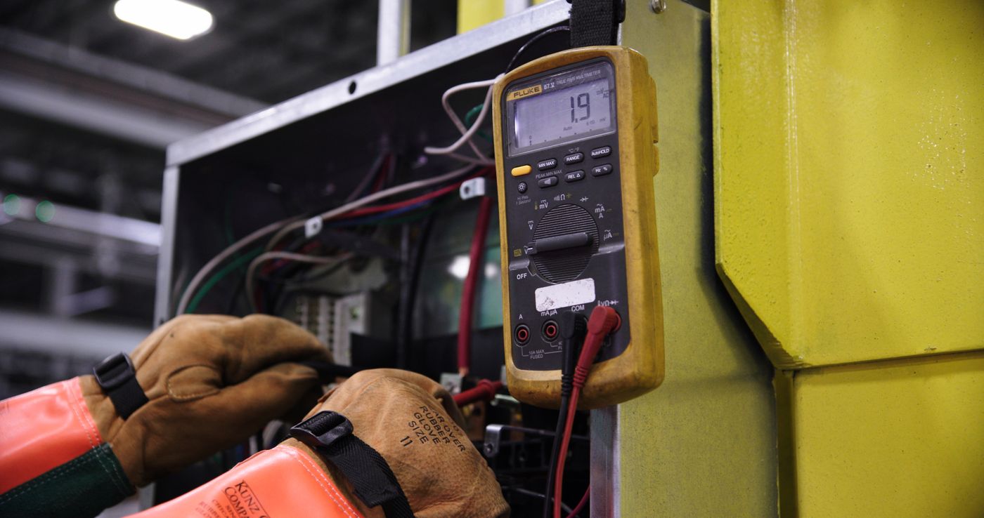
Measure the circuit under load
Do not judge a solid-state output as if it were a dry mechanical contact. On-state voltage drop, off-state leakage current, the PLC input threshold, and connected load all affect the measured value. Use the sensor output diagram and I/O specifications to interpret the reading.
- Measure the sensor supply at the sensor or connector, not only at the power supply.
- Compare output voltage in both states with the PLC input thresholds.
- Check connector pin numbers, cable continuity, shorts, and moisture.
- Observe whether the fault follows machine motion, drive operation, temperature, or cleaning.
Continue with the Sensor Troubleshooting Guide when the symptom remains after installation checks.
Commissioning checklist
Complete these checks before production release
Use the checklist as a commissioning aid. The approved machine procedure and product documentation remain the controlling requirements.
Proximity sensor installation record
Complete every item before release.
Prevent installation faults before ordering
Send XSZ the target, mounting drawing, PLC input, and operating conditions
Include target material and minimum size, nearest/farthest gap, approach speed, surrounding metal, adjacent sensors, supply, input type, required output logic, cable or connector, temperature, contamination, and washdown conditions. We can help identify a more suitable XSZ sensor configuration.
Related decisions
Complete the sensor and PLC specification
Frequently asked questions
Proximity sensor installation FAQ
How far should an inductive proximity sensor be from the target?
Use the assured operating distance and installation conditions published for the exact model, then verify with the real target material, size, overlap, and mechanical tolerance. Do not use Sn or a generic percentage as the final gap without checking these factors.
What is the difference between flush and non-flush mounting?
A flush-mountable inductive sensor can be embedded in surrounding metal as its instructions allow. A non-flush sensor has a larger lateral field and must project beyond nearby metal with a specified free zone. Exact dimensions are model-specific.
What are the three wire colors on a DC proximity sensor?
Brown is commonly +V, blue is commonly 0 V, and black is commonly the switching output on a three-wire DC sensor. Always confirm the model diagram and connector pin numbers because other output types and cable arrangements differ.
How do I know whether the PLC needs a PNP or NPN sensor?
Read the PLC or remote-I/O input circuit. A PNP sensor sources current and typically pairs with a sinking input commoned to 0 V. An NPN sensor sinks current and typically pairs with a sourcing input commoned to +V.
Can a sensor cable run beside motor or VFD cables?
Avoid parallel routing with motor and power wiring where the machine EMC instructions require separation. Use the specified cable, shield, grounding, segregation, and crossing method for the equipment. There is no one universal spacing or single-ended-shield rule for every machine.
Why does the sensor LED switch but the PLC input stay off?
Common causes are a PNP/NPN mismatch, incorrect PLC common, wrong connector pin, open output conductor, insufficient load current, incompatible input threshold, or wrong program address. Compare both wiring diagrams and measure under load.
How tight should I tighten a threaded proximity sensor?
Use the torque or clamping method stated for the exact model, housing material, nut position, and supplied hardware. A generic M8, M12, M18, or M30 torque can damage one product and leave another insecure.
Can temperature or target metal change the sensing distance?
Yes. Inductive operating distance is influenced by target material and dimensions, while the usable or assured distance accounts for stated sensor and environmental tolerances. Use model-specific correction factors and validate the worst operating condition.
Technical references
- IEC 60947-5-2:2019, proximity switches within low-voltage control circuits.
- OSHA: Control of Hazardous Energy, lockout/tagout overview for servicing and maintenance.
- Pepperl+Fuchs: Operating Distance as Central Characteristic, Sn, Sr, Su, Sa, target size, and material factors.
- ifm: Compact Inductive Sensor Installation Guidelines, flush and non-flush mounting near metal.
- Omron E2E NEXT Series Catalog, surrounding-metal distances, mutual interference, torque, and actual-machine validation.
- Omron E2E I/O Circuit Diagrams, typical PNP/NPN three-wire circuits and connector pin arrangements.
- Pepperl+Fuchs: Installation Conditions for Inductive Sensors, metal-free zones and mutual interference.
- ifm IE5129 Product Data, example of model-specific operating distance, correction factors, and tightening torque.
- Rockwell Automation MP-Series Installation Instructions, example EMC guidance for separating signal and power wiring and grounding shields as specified.
Image credits
- Bulat843 / Pexels, industrial hardware installation.
- XSZ Sensor, inductive proximity sensor product formats.
- Bulat843 / Pexels, control-panel wiring.
- Bulat843 / Pexels, production validation.
- Onics Energy / Pexels, electrical measurement.