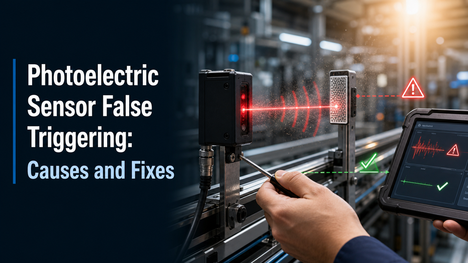
In industrial settings, ambient light, particularly direct sunlight or high-intensity lamps, is one of the main causes of photoelectric sensor false triggering. This is exactly why so many infrared photoelectric sensors rely on modulated light and synchronous detection circuits that only respond to one specific pulse frequency (Sense the World, 2025). Put simply, your sensor sends out a signal when nothing actually crossed its beam, and stray light, dirt, or electrical noise usually ends up taking the blame. This guide answers the questions engineers really do ask.
What actually causes a photoelectric sensor to false trigger? How do you find the underlying root cause quickly? Which fixes stop those nuisance signals for good? And how do the different sensing modes, through-beam, retroreflective, and diffuse, differ when it comes to reliability?
Quick Takeaways
- Ambient light and reflections cause most false triggers on diffuse-mode sensors.
- Modulated IR light rejects background interference by locking to one pulse frequency.
- Choose through-beam sensors for the highest immunity to false triggering.
- Clean sensor lenses weekly to prevent dirt mimicking a real target.
- Set sensitivity margin above 1.5x to stop drift-related nuisance signals.
What causes a photoelectric sensor to false trigger?

A photoelectric sensor false triggering happens when the output changes out of nowhere, even though nothing real is sitting in the beam. There are basically three groups where the root cause tends to live, which are optical, electrical, and environmental. Ambient light, and this really means direct sunlight or those very bright lamps, is a leading cause of false triggering in industrial settings back in 2025. The fix you need depends completely on which group applies, since the output flips from on to off, or off to on, with nothing crossing the beam, and going after the wrong group can waste hours of your time.
What are the three root-cause buckets?
Each group leaves behind its own telltale sign. You want to match the symptom to the right group before you even pick up a screwdriver.
- Optical: this covers stray light, reflections coming off shiny surfaces, or a dirty lens that bends the beam. Diffuse sensors will often lock onto a shiny background rather than the actual target.
- Electrical: this includes electromagnetic interference, which is basically electrical noise, along with noise on the cabling, or a wobbly power supply that shifts the switching point and causes premature activation in 2025.
- Environmental: think vibration, dust, fog, or knocks to the mounting brackets that quietly push the emitter out of alignment without anyone noticing.
Why does sensor mode decide which bucket matters most?
The mode you are running actually changes the type of risk you face. A through-beam pair is the most exposed to mechanical misalignment. A diffuse sensor, which reads the light bounced back off the target itself, is far more likely to run into background-reflection errors. Retro-reflective units land somewhere in the middle. Section 2 goes through each mode in detail.
How do false triggers differ by sensor mode (through-beam, retro-reflective, diffuse)?
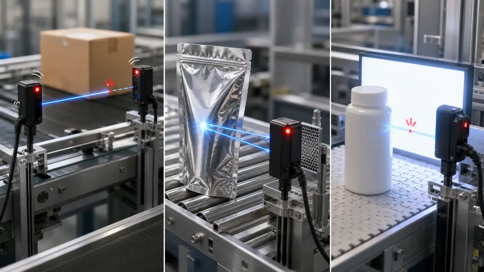
Each sensing mode fails in its own way. Through-beam sensors rarely misfire but lose signal when emitter and receiver drift out of line. Retro-reflective sensors misread shiny targets as their reflector. Diffuse sensors are the most trigger-prone, because they pick up light bounced off backgrounds. Match the fix to the mode, not the symptom.
Why does through-beam almost never false trigger?
Through-beam uses two separate housings: an emitter fires a beam straight into a receiver. There’s no background to reflect off, so photoelectric sensor false triggering from stray light is uncommon. The real weakness is alignment loss. Vibration or a bumped bracket shifts the beam off the receiver window, producing missed detections and unstable output. Manufacturer troubleshooting notes flag emitter-receiver misalignment as a top cause in both through-beam and retro-reflective setups (2024).
Why does retro-reflective misread shiny targets?
Retro-reflective sensors read the beam returning from a corner-cube reflector. A polished target, chrome trim, a wet bag, a mirror-finish can, sends light straight back, so the sensor thinks the reflector is still visible and stays “clear.” The fix is a polarized retro-reflective model, which filters non-polarized reflections from shiny surfaces.
Why is diffuse the most trigger-prone mode?
Diffuse sensors have no reflector at all; they read light bounced off the target itself. That same principle means a shiny conveyor rail or white wall behind the target can return enough light to trip the output. Background reflections are a documented cause of diffuse false triggers (2025). Use background suppression (BGS), which ignores anything past a set distance.
How do you trace a false trigger from symptom to root cause?
Begin with one simple question. Is the false trigger happening at random, or does it repeat the same way every time? A repeatable trip that lines up with the machine’s movement usually points to vibration or an unwanted reflection. A random trip that seems to ignore the machine cycle usually points to electrical noise or stray ambient light.
A more structured way to diagnose this is to use an oscilloscope to correlate sensor output with EMI events or vibration, essentially matching the moment the sensor fires against electrical spikes or shaking. That matters because photoelectric sensor false triggering often comes from a mix of optical, electrical, and mechanical factors working together rather than a single obvious cause. Try not to swap parts at random. If you follow the branches below, you can usually track the fault down in just a few minutes.
Is the trigger timed with machine motion or a fixed cycle?
If the trip repeats at the exact same point in every cycle, you should suspect an optical or mechanical cause. Keep an eye out for a conveyor arm, a shiny fixture, or a reflective product moving past the light beam. Vibration from a nearby press can also shift the alignment just enough to break the beam for a few thousandths of a second. Try tapping the mounting bracket by hand while watching the output LED. If that small movement flips the output, you have confirmed a loose fixture.
Does it fire with no motion and no target present?
Random trips that happen while the machine is sitting idle usually point to electrical or ambient light problems. Check the stability of the power supply first, because a supply ripple, which is a small wobble in the voltage, can shift the switching threshold and cause the sensor to activate too early. After that, block out any direct sunlight or overhead lamps with your hand and watch the output. If the false trigger stops, then the cause was ambient light, and a modulated sensor or a small shroud to shade the sensor will fix it.
How do you check alignment, mounting, and lens contamination?
Start with the sensor’s stability indicator rather than making a guess. This LED, which is often a green “margin” or “stability” light, tells you whether the excess gain, meaning the signal strength above the minimum needed to switch, sits in a safe range. A steady light means the margin is above roughly 2x, while a flickering one warns that you’re near the edge. It’s right at that edge where a dirty lens or reflector and marginal excess gain cause most of the intermittent trips, according to industrial troubleshooting data (2024).
How do you verify beam angle and mounting?
Check the alignment against the target or reflector before you touch the sensitivity setting. For through-beam and retroreflective setups, misalignment between the emitter and the receiver causes both missed detections and false triggers. Loosen and re-aim the sensor until the stability LED peaks, then lock the bracket in place. Vibration or a physical bump can shift a bracket a fraction of a degree, and that’s really enough to drop the margin below 1.5x. It helps to fit vibration-dampening mounts and to inspect the fixtures on a set schedule.
How do you clean the lens without damaging it?
Wipe it dry first, and only go wet if you actually need to.
- Dry microfiber pass: this removes dust and loose grit that would otherwise refract the beam.
- Isopropyl alcohol (approximately 70%[1]+): this cuts through the oil film and coolant mist that dry wiping just smears around.
- Never use paper towels or abrasive wipes: they scratch the anti-reflective coatings, and every scratch scatters light, which basically worsens the photoelectric sensor false triggering that you’re trying to fix in the first place.
For dusty or wet lines, it’s worth specifying IP67 or IP69K housings so that contamination stays off the optics between cleanings.
How does ambient light and reflection cause false triggers?
Ambient light and reflection cause photoelectric sensor false triggering when stray photons hit the receiver at the same wavelength or intensity as the real signal. Ambient light is a leading environmental cause in factories, which is why many IR sensors use modulated light and synchronous detection that only respond to a specific pulse frequency (2025). Match the source to the fix below.
Each interference source fools the receiver differently. Sunlight and incandescent lamps dump broadband energy that can saturate the photodiode. LED and fluorescent lamps flicker at 100,120 Hz[2], and cheap drivers pulse fast enough to mimic a modulated beam. Reflective machinery bounces the emitter’s own light back at odd angles. Dust clouds and welding flash add sudden bursts the receiver reads as an edge.
| Source | Why it fools the receiver | Mitigation step |
|---|---|---|
| Direct sunlight | Broadband saturation of photodiode | Shroud hood + tilt sensor 10–15° downward |
| LED/fluorescent flicker | Pulse mimics modulated signal | Modulated-light sensor with narrow band-pass |
| Reflective machinery | Emitter light bounces to receiver | Polarizing filter (retro-reflective mode) |
| Dust clouds | Scatters beam, false edge | IP67/IP69K housing + air purge |
| Welding flash | Intense IR/UV burst | Optical hood + response-delay filter |
One field trick: aim the sensor so it never points at a low sun angle or a shiny cabinet door. A 12° tilt off the reflective plane usually kills bounce without hurting range.
How do you stop cross-talk between adjacent sensors?
Cross-talk goes away when each sensor can tell its own light apart from a neighbor’s light. The fix is a blend of physical spacing and smart wiring, since sensor vendors list nearby sensors as a major source of false triggers right alongside stray room light. On a tight conveyor, one emitter’s beam bounces into the next receiver, which causes a false switch even when no product is actually there. When two units of the same model share the same modulation frequency, the receiver can’t tell its partner’s pulses from the intruder’s pulses. Start with the cheapest fixes first, and then move on to the electronics.
- Physical staggering: Offset the sensors along the beam axis by 50 to 100 mm[3] so the beams never share a line of sight.
- Opposite mounting orientation: Flip adjacent through-beam pairs head-to-tail. Emitter A points to the left while emitter B points to the right, so the stray light lands behind each receiver instead.
- Alternating light-on / dark-on wiring: Set one sensor to light-on and set its neighbor to dark-on. A crossed beam that trips one logic state gets completely ignored by the other one.
For separation you can count on, use the sensor’s built-in interference protection. A lot of families offer a frequency-select input, which lets you wire adjacent units to channel 1 and channel 2, and then each one responds only to its own pulse train. Others provide a synchronization wire that time-shares the beam, so no two emitters ever fire at the same moment. These inputs basically eliminate photoelectric sensor false triggering from cross-talk without you needing to add shields or brackets.
Check the datasheet’s minimum mounting distance chart before you actually install anything. It lists the safe gap for each range setting.
Is it electrical noise or an optical problem — how do you tell them apart?
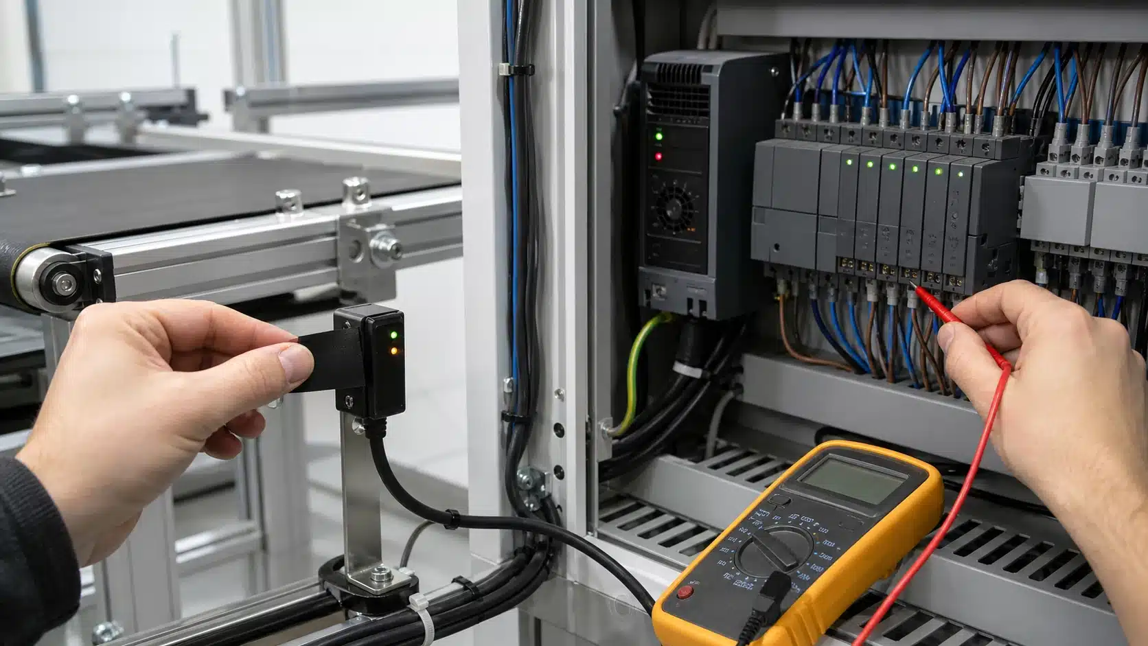
Cover the lens completely with opaque tape. If false triggers stop, the problem is optical. If they persist, the cause is electrical noise, not light. This one test splits your whole diagnosis in half within minutes and points you at the right fix.
Electrical false triggers happen when interference shifts the sensor’s switching threshold. Technical guidance on these sensors confirms that EMI, cable noise, and unstable power supplies can push the output high with no target present. Four culprits dominate:
- Ground loops: two ground points at different voltages force stray current through the signal wire. Fix by grounding the cable shield at one end only.
- Unshielded runs near VFDs: variable frequency drives radiate sharp switching spikes. Keep sensor cable at least 30 cm[4] from drive cables, or use separate metal conduit.
- Inductive load spikes: relays and solenoids kick back voltage when they switch off. Add a snubber (a small RC network) or a flyback diode across the coil.
- Marginal supply voltage: a 24 V[5] sensor drooping to 20 V[6] under load can misfire. Measure at the sensor terminals, not the power supply.
Want proof of the source? Put a scope on the output. Diagnostic procedures recommend using an oscilloscope to correlate sensor output with EMI events. If the false pulse lines up with a nearby motor starting, you’ve your answer. Photoelectric sensor false triggering from noise leaves a signature on the timeline that light problems never do.
What are the most common mistakes when fixing false triggers?
The biggest mistake people make is turning the sensitivity up when a sensor keeps missing its targets, and then they wonder why photoelectric sensor false triggering only gets worse. When you increase the gain, you widen the detection window, so the sensor now “sees” dust, background reflections, and stray light that it used to simply ignore. Manufacturers actually advise doing the opposite, because reducing gain is the standard fix for a sensor that trips even when no target is present (2024).
Here are four so-called “fixes” that usually backfire:
- Cranking up sensitivity: A wider detection window ends up catching noise instead of just the target. If the target is being missed, re-align the sensor first rather than trying to make up for it with more gain.
- Using diffuse mode where retro-reflective belongs: Diffuse sensors, which detect light bounced back off the object itself, will read a shiny background as if it were a target. Using background suppression (BGS), or setting up a retro-reflective arrangement with a corner-cube reflector, fixes this the right way.
- Sharing power with motor drives: Variable-frequency drives, the units that control motor speed, dump electrical switching noise onto any power lines they share. That noise shifts the sensor’s threshold and causes phantom trips. The better approach is to give the sensor its own filtered power supply.
- Cleaning reflectors with solvents: Acetone and other harsh cleaners permanently haze the acrylic surface of corner-cube reflectors. Once the surface is clouded, it scatters the light and drops the excess gain below a safe level. Use only a damp lint-free cloth for cleaning.
Excess gain is really the number that ties all of these problems together, because it measures how much extra light reaches the receiver above the point where the sensor triggers. A dirty lens combined with a marginal amount of excess gain sits among the most common root causes of intermittent trips (2024). Any “fix” that shrinks your margin, such as a hazed reflector, simply pushes you closer to the edge where things stop working reliably. Aim for at least 3x excess gain, and confirm it with the stability LED before you ever touch the sensitivity dial.
Frequently asked questions about photoelectric sensor false triggers
The most common questions about photoelectric sensor false triggering really come down to four things: why the false trips only happen during the day, whether polarized sensors actually fix problems with shiny targets, what sensing margin genuinely means, and when it makes sense to swap out the unit. Sunlight and very bright lamps continue to be a leading cause of false triggers in industrial settings (2025), and that explains most of the faults that only show up in daylight.
Why does my sensor only false trigger during daytime?
It happens because sunlight is flooding into the receiver. If the false trips disappear at night, or when you shade the sensor with your hand, then the ambient light is really the culprit here. What you want is a sensor that uses modulated light along with synchronous detection, which are circuits that only respond to a specific pulse frequency and end up ignoring steady daylight. And it helps to re-orient the lens so it points away from any windows too.
Do polarized retro-reflective sensors solve shiny-target problems?
Yes, in most situations they do. Polarized models rely on a filter that rejects incoming light unless that light has bounced off the corner-cube reflector. A shiny can or a foil pouch reflects light back with the wrong polarization, so the sensor simply ignores it. Standard non-polarized retro units, though, will mistakenly read that shine as if it were their own reflector.
How does sensing margin relate to reliability?
The sensing margin, sometimes called excess gain, is basically how much extra light you have above the point where the sensor trips. You should aim for a margin of at least 4x in clean environments, and 8x or more in places where dust tends to build up over time. Once you drop below 1.5x, any film on the lens or a bit of vibration can cause the sensor to trip on and off intermittently.
When should I replace versus recalibrate a sensor?
Try to recalibrate it first. That means you clean the lens, re-align the unit, and reset the sensitivity. You should only replace it when the housing is cracked, when the LED emitter has dimmed below where it should be, or when the false trips keep happening even after alignment and cleaning have restored the full margin.
Putting the diagnostic workflow into practice
Run a photoelectric sensor false triggering diagnosis in three moves: identify the mode, cover the lens, then check the margin LED. Structured diagnostics that correlate sensor output with EMI or vibration events (2025) confirm that false triggers usually come from combined optical, mechanical, and electrical faults, not one cause. So test in order, and stop guessing.
Match the symptom to the mode first. A through-beam trip points to alignment or a blocked emitter. A retro-reflective trip usually means a shiny target beat the polarizing filter. A diffuse trip almost always means a background surface got read as the target, fix it with background suppression, not more sensitivity.
Then run the cover-the-lens isolation test. Tape the lens fully opaque. Triggers stop? The problem is optical, ambient light, dirt, or reflection. Triggers continue? It’s electrical, EMI, grounding, or an unstable supply.
What checklist should you run on the floor?
Work this list in order, top to bottom:
- Stability LED: confirm green margin light stays solid, not flickering
- Lens and reflector: wipe clean; recheck margin after
- Alignment: re-peak through-beam and retro-reflective pairs
- Cover-lens test: separate optical from electrical faults in 30 seconds
- Cabling: verify shielded cable, single-point ground, filtered power
Close every job by writing it down. Log the sensitivity setting, sensing distance, margin reading, and cable routing on a card at the machine. When the next false trigger hits, a technician compares today’s margin to the baseline in seconds instead of restarting the whole workflow.




