
Industrial sensor troubleshooting
How to Fix a Proximity Sensor Not Detecting Metal
Start with a known metal target and separate four observations: sensor power, sensor indicator, electrical output, and PLC input. Most failures come from the wrong target or distance, incorrect mounting, a PNP/NPN or NO/NC mismatch, damaged wiring, or a sensor that is unsuitable for the metal and environment.
- Known-target sensing test
- PNP, NPN, NO, and NC checks
- Flush mounting, interference, and replacement
Inspection setup photo: Joongbae Kim, Wikimedia Commons, CC BY-SA 3.0.
Read the supply, output, rated target, setting distance, and mounting instructions from the label and datasheet.
Present a sufficiently large mild-steel target inside the model's stable operating range and watch the sensor indicator.
If the indicator changes, test the output with the correct load and confirm PNP/NPN and NO/NC compatibility.
Confirm power, target, gap, mounting, wiring, and load before declaring the sensing element or output stage defective.
Control hazardous energy before touching the sensor or machine
Apply the site's energy-control procedure before adjusting brackets, cleaning a sensing face near moving parts, opening wiring, or entering a guarded area. A PLC stop command, sensor output, selector switch, or indicator is not an energy-isolating device.
Live voltage or output measurements should be performed only by qualified, authorized personnel under a controlled test procedure. If temporary energization is essential, clear tools and people, energize only for the test, then de-energize and reapply the required energy controls before continuing work. Follow local requirements and the machine-specific risk assessment.
Choose the observed symptom
Where does the detection chain stop?
Select what you see at the machine. The next checks change depending on whether the fault occurs at the sensor, its output, or the PLC.
Verify power at the sensor, not only at the cabinet
A dark indicator does not by itself prove a failed coil. Some models use the LED only for output state, while others have separate power and output indicators.
- Read the exact operating-voltage range and pinout.
- With an authorized live-test procedure, measure between the sensor's positive and 0 V terminals at the sensor connection.
- Inspect the fuse, terminal, cable, connector pins, splitters, and common return.
- Correct reverse polarity, excessive voltage drop, or an overloaded supply before retesting.
Next evidence: correct voltage at the sensor terminals under load.
Run a controlled known-target test
Do not start with the production target if its alloy, size, position, or path is uncertain.
- Confirm that the device is an inductive sensor intended to detect metal.
- Clean the active face and inspect it for impact, abrasion, swelling, or weld damage.
- Use a sufficiently large mild-steel target inside the model's specified set distance.
- Check flush, non-flush, or semi-flush installation and surrounding-metal clearance.
- If the LED still does not change, test the same sensor away from the original metal bracket when the manual permits.
Next evidence: the indicator changes with a known target in the approved installation.
The sensor is detecting; now trace the electrical state
An operating LED can change even when the PLC never receives a valid voltage or current.
- Confirm PNP or NPN and whether the active function is NO, NC, or complementary.
- Compare the sensor output diagram with the PLC input common and input type.
- Measure the output with the specified load connected; do not rely on an unloaded meter reading alone.
- Check the black output conductor, M12 pin assignment, input terminal, PLC channel LED, tag mapping, and program inversion.
Next evidence: output changes at the sensor and at the PLC terminal, then the PLC tag changes.
Move the application away from its switching edge
Intermittent detection usually needs a margin investigation rather than an immediate sensor replacement.
- Record the actual ON and OFF points to reveal hysteresis and vibration effects.
- Apply the exact material correction factor and target-size guidance.
- Remove accumulated metal powder or chips and verify bracket rigidity.
- Check mutual-interference spacing, high-current cable separation, temperature, connector movement, and supply dips.
Next evidence: stable switching across target, temperature, vibration, and full machine operation.
Fast troubleshooting order
Use this five-step sequence before changing the sensor
Each step produces evidence for the next one and avoids replacing a healthy sensor while leaving the real wiring or application fault in place.
Identify
Record the full model, sensing principle, supply, output, switching function, connection, rated target, and installation type.
Inspect
With energy controlled, check the target path, gap, bracket, face, cable, connector, metal chips, impact, and surrounding metal.
Prove sensing
Use a known steel target at the specified stable set distance and observe the sensor indicator away from uncertain process variables.
Prove output
Under an authorized electrical test, verify supply and loaded output against the model's PNP, NPN, NO, NC, or 2-wire diagram.
Prove the system
Trace the state through the cable, PLC terminal, channel indicator, tag, program logic, machine cycle, and environmental extremes.
Target and distance
Why a sensor detects steel but misses aluminum, brass, copper, or stainless steel
An inductive sensor creates an alternating electromagnetic field at its active face. A metal target changes the oscillator through eddy-current losses and, for magnetic materials, permeability effects. The amount of damping depends on the sensor design as well as target material, alloy, size, thickness, approach direction, and distance.
The rated sensing distance is normally established with a defined standard target, often steel. It is not a guaranteed distance for every real machine part. Manufacturers publish a material correction or reduction factor for conventional inductive models. Factor-1 or all-metal models are designed to reduce this material dependence, but their exact assured distance still comes from the individual datasheet.
Typical values help explain a fault, but housing, shielding, coil design, alloy, and sensor family change the result. Use the factor and setting distance for the exact part number.
Target size matters too
A small bolt head, thin sheet edge, wire, tooth, or off-axis target can switch closer than the catalog's standard target. A larger target usually offers little extra range after it fully covers the useful field, while a smaller target can reduce range sharply. Recreate the real approach direction and speed during validation.

Typical reference value for a conventional inductive sensor.
Composition and magnetic behavior can change the result significantly.
Verify the exact model or use a suitable factor-1 design.
Alloy and target geometry can move the switching point.
Use a measured validation margin rather than the upper estimate.
Typical ranges are engineering examples reported by industrial sensor manufacturers, not XSZ model specifications or universal limits.
Some product guides define the set distance at roughly 70% to 80% of the normal rated distance for the specified standard target. Treat the exact product value, assured operating range, tolerances, and application test as controlling. Do not automatically multiply every sensor by 0.8.
Installation faults
Check flush mounting, surrounding metal, the sensing face, and target alignment
A correct target can still disappear when the installation changes the electromagnetic field or the physical gap moves during the cycle.
Designed for embedding in metal
Internal shielding concentrates the field toward the front, allowing the active face to be mounted flush under the specified conditions.
- Do not assume every long-range model is fully flush mountable.
- Check front clearance, mounting nut position, and nearby moving metal.
- Verify the target approaches the reference axis shown in the datasheet.
Requires a metal-free zone
The field spreads around the active end, so surrounding steel can shorten, extend, latch, or destabilize the switching behavior.
- Let the sensing face project as the model drawing requires.
- Use the specified side, front, and mutual-interference clearances.
- Do not copy a generic multiple of sensor diameter to every model.
Clean metal accumulation, but diagnose what it was doing
Nonmetallic oil or coolant is not automatically invisible to the complete installation, but a thin clean film normally does not behave like an extra millimeter of metal target. The larger problem is often metal powder or chips held in the fluid, a damaged seal that allows ingress, or a deposit that keeps the sensor continuously damped.
Record whether the sensor was stuck ON, failed to reset, or had a shortened practical gap before cleaning. Inspect the active face for cuts, impact marks, melted plastic, weld spatter, swelling, and abrasion. Never use the sensor as a mechanical stop.
Verify alignment through the whole cycle
Check bracket torque, shaft play, conveyor movement, actuator end position, target tilt, and vibration. Measure the minimum target overlap and maximum gap, not only the machine at rest. The switch and release points differ because inductive sensors have hysteresis; a target that barely turns the output ON may chatter as it moves away.
Output compatibility
Confirm PNP or NPN before testing the black output wire
Brown, blue, and black are common IEC-style conductor colors for 3-wire DC sensors, but the exact wiring diagram and connector pinout for the model always take priority.
Typical 3-wire PNP sensor
Usually connects to the permitted positive DC supply.
Usually connects to 0 VDC or L-.
Sources positive voltage to a load or sinking PLC input when active.
The load is typically between output and 0 V. Confirm input common, maximum load current, residual voltage, and protection behavior.
Typical 3-wire NPN sensor
Usually connects to the permitted positive DC supply.
Usually connects to 0 VDC or L-.
Sinks current toward 0 V for a load or sourcing PLC input when active.
The load is typically between positive supply and output. Confirm that the PLC input type and common are compatible.
A PNP or NPN sensor can be normally open, normally closed, programmable, or complementary. Compare the timing chart with the PLC program. Use the NPN vs PNP Sensors guide and NO vs NC Sensor Output guide when the indicator changes but the control logic appears inverted.
Electrical evidence
Test supply and output without creating a new fault
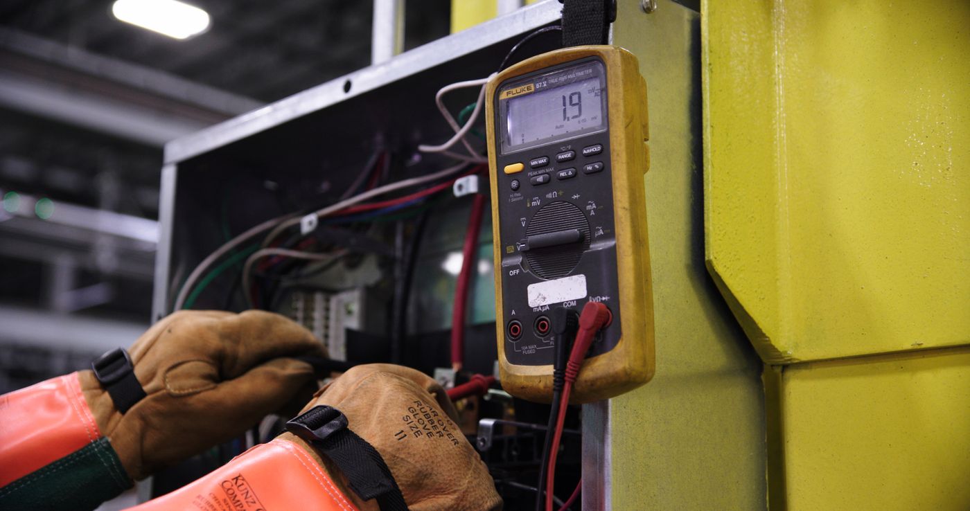
Do not assume every 3-wire sensor uses 10-30 VDC. Read the model label first. During an authorized live test, place the meter's red lead on the specified positive supply terminal and black lead on 0 V to check sensor voltage. Measuring at the power supply alone can miss cable drop, a loose connector, or a poor common.
Test the output with the intended load
An unloaded digital multimeter may display a voltage caused by leakage, diagnostic current, pull-up circuitry, or the PLC input. Test the sensor in the circuit defined by its output diagram and remain below the output current rating. Do not connect an arbitrary test lamp: its inrush current can overload a small transistor output.
Do not forget 2-wire behavior
A 2-wire electronic sensor is powered through its load. It has an OFF-state leakage current and an ON-state residual voltage. A high-impedance PLC input may remain falsely ON from leakage, while a low-voltage load may fail to energize because too much voltage remains across the sensor. Use the model's load-current window and the PLC input specification.
An LED that is dark with correct supply does not prove a failed sensing coil, and an LED that is lit does not prove the output transistor or external circuit is healthy. Read the indicator definition and test each layer.
Trace the state
Use the LED, output voltage, PLC channel, and program tag as separate checkpoints
This matrix avoids the common mistake of calling every missing PLC signal a sensor detection failure.
Confirm sourcing versus sinking, input common, active-high versus active-low interpretation, NO/NC function, and the actual tag address before replacing hardware.
Intermittent and repeat faults
Look beyond the sensor when detection changes with the machine cycle
Temperature, electrical noise, nearby sensors, vibration, cable motion, and welding fields can reduce operating margin or create a false state.
Mutual interference
Two inductive sensors can interact when their oscillator fields overlap. Required spacing depends on sensor diameter, rated distance, flush/non-flush design, orientation, and frequency. Use the model's mounting diagram. Where close installation is unavoidable, select sensors with an interference-prevention function or offset frequencies.
EMI, power disturbance, and welding
Route sensor cables separately from motor, contactor, heater, VFD output, and welding conductors as the product and machine instructions require. Inspect cabinet bonding, cable shield continuity where applicable, surge suppression, and 24 VDC dips during solenoid or contactor operation. Near resistance welding, use a model specifically rated for weld-field immunity and spatter exposure.
Temperature and mechanical stress
Operation outside the rated temperature range can shift switching and release points and eventually damage electronics, resin, seals, or cable. Cable flexing near the molded exit, excessive connector strain, a loose bracket, or a target that moves with thermal expansion can create cycle-dependent dropouts.
Inspect cable and alignment
Watch target overlap, bracket movement, connector strain, cable flex, and intermittent conductor continuity.
Inspect supply and EMC
Capture sensor voltage, output, grounding, routing, and transient suppression during the exact event.
Inspect temperature margin
Compare ambient and sensor temperature with the rating and recheck the target inside the stable set distance.
Make an evidence-based decision
When should you keep, replace, or upgrade the proximity sensor?
Choose the action that removes the verified root cause. A like-for-like replacement will not fix an unsuitable target, incompatible PLC input, or incorrect mounting pocket.
The sensor passes a controlled test
Keep it when it switches reliably with the known target and correct load. Correct the target gap, bracket, mounting clearance, connector, PLC common, program logic, routing, or contamination that caused the field failure.
The sensor or lead is physically or electrically damaged
Replace it when the active face is cracked, abraded, swollen, melted, or impact-damaged; the integral lead is broken; ingress is visible; or it fails the manufacturer's known-target and loaded-output test with correct power and installation.
The application exceeds the current sensor class
Consider factor-1 for varying metals, longer-range models for mechanical margin, shielded or non-flush geometry that matches the pocket, weld-field-immune versions, higher temperature or ingress ratings, robust cable, or IO-Link diagnostics.
Capacitive sensors can detect metal and nonmetal materials but introduce sensitivity to surrounding material, moisture, deposits, and adjustment. Compare a conventional inductive, factor-1 inductive, photoelectric, or other technology against the complete task. Start with the How to Choose Industrial Sensors guide.
Prevent repeat failures
Record the operating margin, not just the replacement part number
A short installation record makes the next fault faster to diagnose and prevents a maintenance replacement from changing a critical sensor characteristic.
Record the full model
Include sensing range, flush type, output, NO/NC function, connector, cable, temperature, and environmental rating.
Record the real target
Document alloy, dimensions, thickness, approach direction, speed, minimum overlap, and maximum operating gap.
Mark the stable set position
Measure ON and OFF points, then set the working position within the manufacturer's stable region with vibration allowance.
Inspect mounting and deposits
Include bracket movement, surrounding-metal clearance, target damage, active-face impact, and accumulated metal powder.
Trace the electrical chain
Label the output type, M12 pins, input common, PLC channel, tag, logic state, fuse, splitter, and junction locations.
Validate at operating extremes
Test minimum and maximum target position, cold and warm conditions, full machine noise, production speed, and cable movement.
Need help choosing a sensor that reliably detects your metal target?
Send the current sensor model, target alloy and size, minimum and maximum gap, mounting drawing, supply, PNP/NPN and NO/NC requirement, PLC input, temperature, contamination, and switching speed. XSZ can help narrow the correct sensor class before replacement.
Continue troubleshooting
Related XSZ sensor guides
Use these pages to resolve the next decision without guessing at an unpublished product or application page.
Need a different sensing method? Compare the Photoelectric Sensors Overview, review How to Choose Industrial Sensors, or browse the Sensor Knowledge Center.
Frequently asked questions
Proximity sensor not detecting metal FAQ
Short answers for common field symptoms and replacement decisions.
Why does my inductive proximity sensor detect steel but not aluminum?
Conventional inductive sensors are often rated with a steel target. Aluminum usually has a lower model-specific correction factor, so the usable switch distance can be much shorter. Move the target into the exact sensor's stable set distance or select a suitable factor-1 sensor after validating the alloy, size, and mounting.
How can I test an inductive proximity sensor without a PLC?
Use the manufacturer's circuit, a current-limited supply within the exact operating range, and a compatible load for the PNP, NPN, or 2-wire output. Present a known steel target inside the set distance and measure the loaded output. Do not use an arbitrary test lamp or guess the connector pins.
What voltage should I measure at a 3-wire proximity sensor?
Measure the voltage specified on the exact model, at the sensor terminals and under load. Many industrial 3-wire sensors use 24 VDC systems, but the permitted range is product-specific. With common color coding, red meter lead goes to positive or brown and black meter lead to 0 V or blue, after the pinout is confirmed.
Why does the sensor LED switch but the PLC input stay OFF?
The sensor may be detecting while the output circuit is incompatible or disconnected. Check PNP versus NPN, NO versus NC, PLC input common, black output conductor or M12 pin, loaded output voltage, input terminal, physical channel indicator, tag address, and program logic.
What is the difference between flush and non-flush proximity sensor mounting?
A flush or shielded inductive sensor is designed for embedding in metal under its specified conditions. A non-flush or unshielded sensor normally provides more range but needs a metal-free zone around the active end. Use the model drawing because clearance and mutual-interference distances are not universal.
Can metal chips on the sensing face stop detection?
Yes. Accumulated metal powder or chips can keep the field damped, prevent reset, or reduce useful margin. Control energy, clean the face using the approved method, inspect for damage or ingress, then repeat the known-target test and correct the source of the contamination.
How do I know the proximity sensor itself is bad?
Suspect the sensor after the exact supply, pinout, load, known target, set distance, mounting clearance, cable, and connector are verified and the sensor still fails its manufacturer-defined test. Physical face damage, ingress, a broken integral lead, or a loaded output that cannot switch are stronger replacement evidence than LED state alone.
Should I replace an inductive sensor with a capacitive sensor for non-ferrous metal?
Not automatically. A capacitive sensor can detect metal but may also respond to nearby nonmetals, moisture, or deposits. Compare a conventional inductive sensor at a shorter gap, a factor-1 inductive sensor, a photoelectric sensor, and other technologies against the real target, environment, speed, and mounting space.
Technical references
Sources used for troubleshooting context
- OSHA 29 CFR 1910.147: Control of hazardous energy
- OSHA: temporary energization for testing or positioning
- Pepperl+Fuchs: inductive sensor operating distance and reduction factors
- Balluff: typical material correction-factor ranges
- Pepperl+Fuchs: installation conditions for inductive sensors
- OMRON: proximity sensor technical guide and set-distance terminology
- OMRON: proximity sensor wiring, environment, and inspection precautions
- OMRON E2E catalog: example NPN and PNP output circuits
- Pepperl+Fuchs: inductive sensor fault-repair checks
Technical guide updated July 2026. Final installation and test values must come from the exact sensor, cable, PLC input, machine risk assessment, and applicable local requirements.