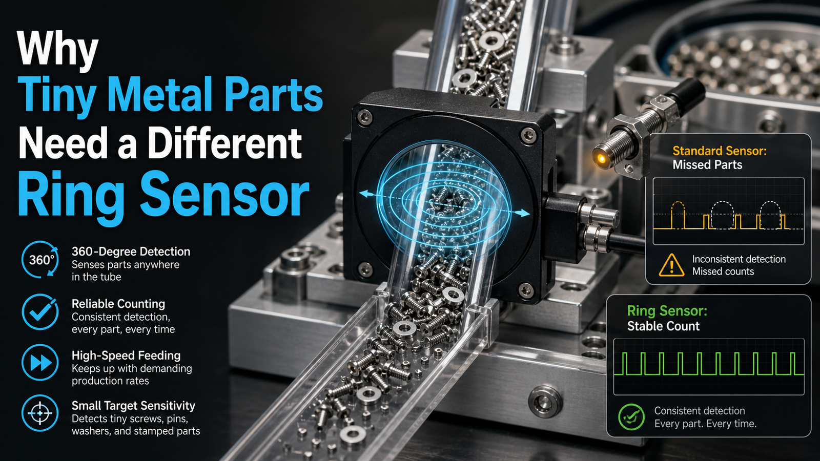
Ring sensor small parts detection uses inductive coils encircling a bore to detect tiny metal objects moving through see-through feeding hoses, rather than reading from a single flat face like standard proximity switches. These sensors catch parts traveling at several meters per second, making them ideal for high-speed sorting lines. Analog-output versions go further, measuring part size and thickness instead of just confirming presence, which enables sorting of screws, springs, and stampings on vibratory feeders where flat sensors consistently fail.
This guide answers the questions engineers actually tend to ask. How does a ring sensor differ from a flat inductive switch? What parts make up the sensor and the coil assembly? Which specifications matter most when you’re picking one, meaning the bore diameter, the detection speed, and whether you want analog or switching output? And where do these sensors really earn their keep on real feeding lines?
Quick Takeaways
- Ring sensors detect metal inside the bore, not from one flat face.
- Top models handle part streams moving several meters per second.
- Analog-output versions measure part size and thickness, not just presence.
- Match bore diameter to your feeding hose—the top selection spec.
- Best for sorting tiny screws, springs, and stampings on vibratory feeders.
What’s a ring sensor and how does it detect small parts?
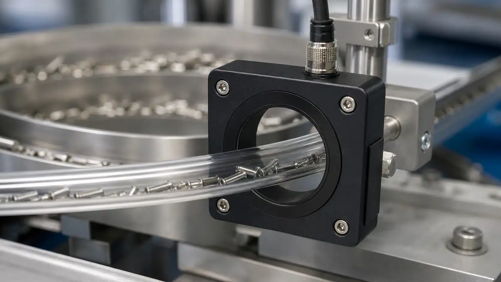
A ring sensor spots parts moving through its circular opening, which is called the aperture, by keeping an eye on a field or beam that fills that space. Whenever an object passes through the ring, it disrupts the field and sets off a signal. The inductive kind can pick up metal spheres as small as roughly 0.7 mm in diameter as of 2025, which basically makes ring sensor small parts detection doable in situations where ordinary proximity sensors just can’t manage.
You can picture the aperture as a doughnut hole with an invisible tripwire stretched right across it. An inductive ring creates an electromagnetic field inside the opening. When a metal screw or a nail goes flying through, it pulls energy out of that field, and the sensor reads the dip that happens. Optical rings work with a light beam instead, and capacitive rings respond to changes in electrical charge.
The tricky bit with really tiny metal parts comes down to the shape of the field, which is essentially field geometry. The density is at its strongest right at the ring wall and at its weakest at the dead center. A large part takes up most of the aperture, so it disturbs the field no matter where it happens to travel. A 1 mm screw passing through the middle, though, might barely register at all.
This is exactly why speed and signal timing end up mattering so much. Fast-moving small parts go through in under a millisecond, so good sensors add a pulse extension of around 150 ms to hold the signal long enough for a counter to actually read it. If you skip this step, your PLC will miss hits when the feed rates get high.
Why do tiny metal parts need a different sensor than large ones?
Tiny metal parts need a sensor with a tighter detection limit because the signal shrinks with part volume, not diameter. A 0.5mm pin has roughly 1,000 times less metal mass than a 5mm screw. Even good inductive ring sensors bottom out near a 0.7mm metal sphere as of 2025, so a sensor tuned for screws will simply not register the pin.
Here is the physics. A ring sensor generates an electromagnetic field across its aperture (the circular opening). A passing metal part disturbs that field, creating a signal. But the disturbance scales with the part’s volume relative to the whole aperture. Shrink the part 10x in each dimension and the field change drops far below the sensor’s noise floor, the background electrical “hiss” every sensor produces.
Why does signal-to-noise ratio matter more than the rated range?
Signal-to-noise ratio matters more than rated range because a spec sheet’s “detects metal” claim hides the noise floor. Signal-to-noise ratio (SNR) is the useful signal divided by that background noise. For ring sensor small parts detection, a 0.5mm pin in a 22mm aperture may produce an SNR below 3:1, too weak to trigger reliably.
- Aperture-to-part ratio: keep it under 40:1 for micro-parts; a 22mm ring chasing a 0.5mm pin sits at 44:1, past the safe edge.
- Detection limit spec: demand the minimum detectable sphere size in mm, not “sensitivity: high.”
- Response time: under 1ms is standard for fast lines, per 2025 ring sensor specs.
Skip any sensor that quotes range but hides its smallest detectable diameter. That number, not marketing, tells you if it will catch your pin.
How small a part can a ring sensor actually detect versus its aperture diameter?
A ring sensor can reliably spot parts that are somewhere between one-fifth and one-tenth the size of its aperture, which is simply the opening the part passes through as it drops. So an 8mm ring will catch metal parts as small as about 0.8 to 1.6mm across. Typical inductive ring sensors, meaning the kind that senses metal by the way it disturbs a magnetic field, can pick up metal spheres down to roughly 0.7mm in diameter when you use the smallest openings, so you really want to match the ring to the part and avoid making it any bigger than it needs to be.
An oversized ring works against you because the magnetic field is at its strongest right at the edge of the coil and at its weakest in the center of the opening. A tiny screw drifting through the middle of a 30mm ring hardly disturbs that field at all. When you shrink the opening, though, that same screw fills up more of the field, and that gives you a signal strong enough to actually set a reliable trigger point on.
What minimum part size can each aperture realistically detect?
The size of the opening you choose sets the lower limit for ring sensor small parts detection. The table below pairs common inner diameters with the realistic smallest metal parts you can catch, based on that 1:5 to 1:10 ratio.
| Aperture (inner diameter) | Min. detectable part (1:10) | Comfortable detection (1:5) |
|---|---|---|
| 3mm | 0.3mm | 0.6mm |
| 8mm | 0.8mm | 1.6mm |
| 15mm | 1.5mm | 3.0mm |
| 30mm | 3.0mm | 6.0mm |
The practical guideline is to pick the smallest ring that still leaves room for your largest part along with the wall thickness of the feed tube. Every extra millimeter of aperture raises the smallest size you can detect and reduces how sensitive the sensor is to the tiniest fasteners.
Inductive vs capacitive vs optical ring sensors — which fits tiny metal parts?
For very small metal parts, inductive ring sensors come out ahead. They can detect ferrous spheres down to roughly 0.7 mm in diameter as of 2025, they ignore dust and plastic entirely, and they respond in under 1 ms. Capacitive rings, on the other hand, catch non-metals such as plastic or glass, and optical rings count by breaking a light beam. Both of those, though, struggle in the situations where inductive sensors really do their best work.
The real difference comes down to what each sensor is actually able to “see.” An inductive ring reacts to eddy currents, which are tiny electric swirls that a metal part stirs up inside its magnetic field. Ferrous metals like steel screws boost that signal quite a bit, so inductive types are the natural choice for ring sensor small parts detection in screw feeders and vibratory bowls.
How do the three technologies compare on tiny parts?
Inductive rings handle the smallest metal, capacitive rings handle non-metals, and optical rings will count just about anything opaque, but reflective steel confuses the optics badly.
| Technology | Detection principle | Smallest reliable part | Best material |
|---|---|---|---|
| Inductive | Eddy currents in metal | ~0.7 mm sphere | Ferrous / steel |
| Capacitive | Dielectric change | ~2 mm | Plastic, glass |
| Optical | Beam interruption | ~1 mm opaque | Non-reflective solids |
Why do optical rings fail on shiny metal?
Optical rings fail on shiny metal because a polished surface scatters or reflects the beam right back into the receiver, which fakes a “no part” reading. A chrome screw can end up looking like empty air to the sensor. It is generally better to skip optical for bright ferrous micro-parts and pick an inductive ring instead.
How do you size the ring aperture for micro-part counting?
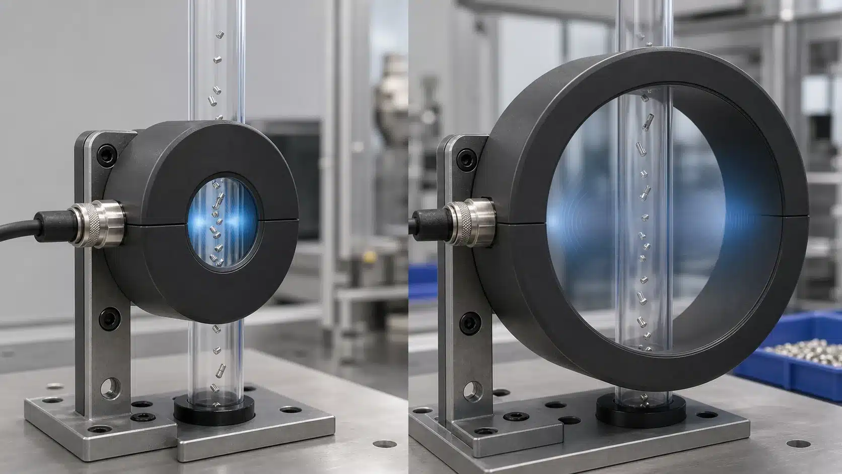
Pick the smallest aperture that still gives your part a clear path. A good starting rule: aperture inner diameter should be 1.5 to 2 times the widest cross-section of the part plus its feed tube. Since a ring sensor’s small parts detection sensitivity drops sharply as the opening grows, every extra millimeter of clearance costs you detection margin.
⚠️ Common mistake: Oversizing the bore diameter “for safety margin,” then missing small screws entirely. This happens because the inductive field weakens toward the center of a large aperture, so a tiny part passing through the middle barely disturbs it. The fix: match the bore to your feeding hose diameter as closely as possible—a snug bore keeps small parts within the sensitive detection zone.
Why does a smaller aperture beat a bigger one for sensitivity?
A smaller aperture beats a bigger one because the magnetic field spreads out as the ring gets wider, so beam density (field strength per unit of cross-section) falls fast. A part in a 10mm ring sees a much denser field than the same part in a 27mm ring. Typical inductive units detect metal spheres down to about 0.7mm in a 10mm ring as of 2025, but that floor rises quickly with a larger opening.
How do you size a ring for feeding 1mm rivets?
Say your rivets are 1mm wide and run through a 4mm outer-diameter feed tube. The tube sets the real minimum. Add approximately 30% flow clearance: 4mm × 1.3 ≈ 5.2mm. Round up to a stock 6mm or 8mm aperture.
Skip the 10mm ring, that extra 2mm cuts sensitivity for no benefit. A 6mm ring keeps beam density high enough to catch the 1mm rivet reliably while the tube slides through without jamming.
What failure modes cause a ring sensor to miss tiny parts?
Ring sensors miss tiny parts for three overlooked reasons: static cling pins parts to the tube wall outside the sensing zone, clustered parts read as one object, and clear or shiny materials fool optical rings. Each has a distinct symptom and a specific fix. Solve the physics, not the count.
Why do static-charged parts stick to the tube wall?
Static cling holds light plastic or coated parts against the hose wall, where they slip past the aperture edge instead of passing through the strongest signal zone. Symptom: your count drops on dry days or after long runs of the same material. Fix: ground the metal tube, add an ionizing air blow-off at the feed inlet, or switch to anti-static tubing. Inductive ring sensors reading metal are less affected, since the coil senses the whole cross-section.
What happens when parts clump together?
Two screws touching as they pass generate one signal pulse, not two, so a batch of 500 counts as 470. Symptom: totals run consistently low, worse at high feed rates. Fix: use a sensor with a tuned pulse extension,around 150 ms in 2025 industrial ring sensor specs,so the output resets cleanly between parts, and space the feed rate below the sensor’s response window.
Why do optical rings fail on clear or shiny parts?
Transparent glass or highly reflective chrome parts pass light straight through or scatter it, so the optical beam never registers a break. This is the core weakness of optical ring sensor small parts detection. Fix: switch to an inductive ring for metal or a capacitive ring for glass and plastic, since both sense material presence, not light blocking.
Ring sensor vs area sensor vs through-beam for micro-part counting
For counting tiny metal parts moving fast through a tube, a ring sensor wins. It detects metal spheres down to roughly 0.7 mm as of 2025 and confirms each part with no gap to align. Area sensors and through-beam setups fit open conveyors and mixed-material sorting, not enclosed high-speed feeding.
The three approaches solve different problems. A ring sensor surrounds the part on all sides, so a screw can tumble in any orientation and still register. A through-beam sensor sends one light beam across a gap, a part must break that beam to count. An area sensor (light curtain) uses a grid of beams to cover a wide zone.
| Approach | Min. detectable size | Best throughput | Count accuracy on micro-parts | Relative cost |
|---|---|---|---|---|
| Inductive ring sensor | ~0.7 mm metal | Up to ~20 m/s in tubes | High (360° coverage) | Low–medium |
| Through-beam | ~1–2 mm (beam width limit) | Moderate | Drops if parts overlap | Low |
| Area sensor / light curtain | ~2.5 mm (beam pitch) | High on wide belts | Poor for tiny clustered parts | High |
Pick a light curtain when parts spread across a wide belt and you count larger items. Pick through-beam for one-at-a-time gating of parts above 2 mm. But for enclosed hose feeding of screws, nails, or micro-pins at speed, ring sensor small parts detection stays the cleaner call, no beam alignment, no ambient light drift, and reliable counting even in dusty feeders.
How to choose a ring sensor for metal, plastic, or mixed parts
Match the sensor tech to the material first, then size the aperture. Inductive rings detect metal parts down to 0.7 mm spheres, while capacitive versions catch non-metallic parts like plastic or glass, according to 2025 ring sensor catalog data. Mixed streams usually force a hybrid or optical setup, no single field-based sensor reads both cleanly.
Which sensor type fits your material?
Use this if-X-then-Y guide to skip trial and error.
| Material | Part size | Best sensor type |
|---|---|---|
| Metal (steel, screws) | 0.7–5 mm | Inductive ring |
| Plastic, glass, rubber | Any | Capacitive ring |
| Mixed metal + non-metal | Any | Optical or hybrid |
| Fast metal in tubing | Sub-mm | Inductive with pulse extension |
Why do mixed streams push you toward optical?
Mixed streams push you toward optical because inductive fields ignore plastic, and capacitive fields react to moisture and hose walls, giving false counts. When both material types flow through the same tube, an optical ring, which sees any object that blocks light, handles the job. This is the core challenge in ring sensor small parts detection when feed lines carry varied components.
Avoid over-specifying. A 20 m/s speed rating and 150 ms pulse extension matter for high-speed feeders, but a slow screw drop needs neither. Buying that spec wastes budget and adds no accuracy.
Common setup mistakes that cause missed detections
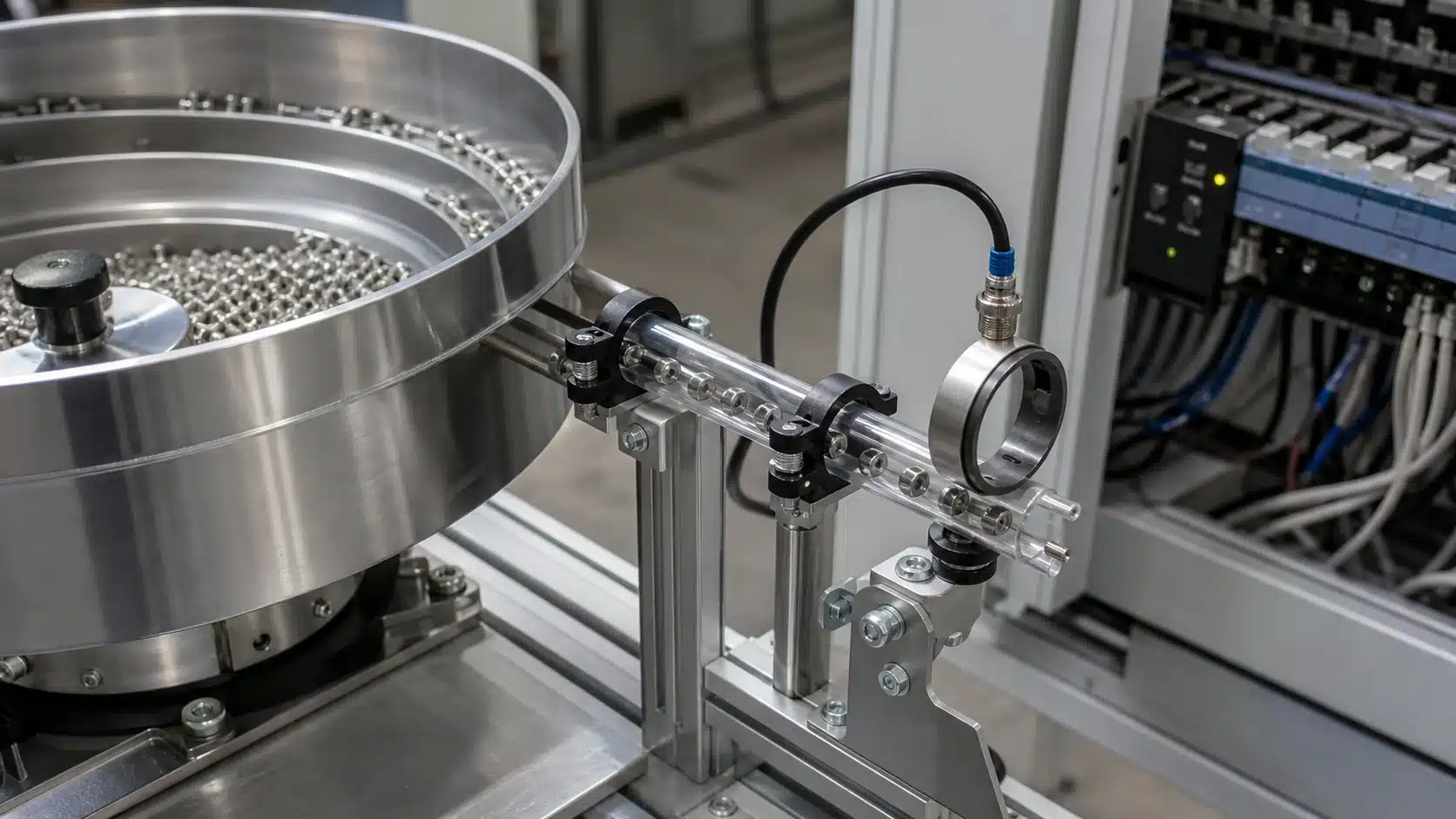
Most missed detections come from four fixable install errors: mounting the ring too far from the drop point, setting the wrong sensitivity threshold, feeding parts too close together, and ignoring vibration. Each one has a field fix that takes minutes. Ring sensor small parts detection fails far more often from bad setup than bad hardware.
Why does mounting distance ruin the count?
Mounting distance ruins the count because a ring set too far from where parts leave the tube lets them tumble and spread sideways. The signal weakens fast as a part drifts off the axis. Keep the aperture within 30,50 mm of the drop point so parts pass through the center. Fix: shorten the free-fall gap or add a guide tube that ends inside the ring.
How do you set the right sensitivity threshold?
Teach the threshold using your actual smallest part, then drop it 10,approximately 15% for margin. Set it too high and a 0.7 mm screw slips through unseen; set it too low and vibration triggers false counts. Some inductive rings detect metal spheres down to roughly 0.7 mm in diameter as of 2025, but only when tuned to your smallest part.
Two more killers: parts stacked closer than 150 ms apart merge into one count,slow the feed or widen the gap. And unbraced tubing vibrates against the ring, adding noise. Clamp the tube 20 mm before and after the aperture. These four checks recover most lost counts before you blame the sensor.
Frequently asked questions about ring sensors for small parts
Ring sensors for small parts detection raise the same four questions from nearly every buyer: minimum part size, counting behavior, speed limits, and enclosure ratings. Below are direct answers with real specs. Typical inductive rings detect metal spheres down to about 0.7 mm as of 2025, small enough for tiny screws, pins, and wire ends.
What’s the smallest part a ring sensor can detect?
Around 0.7 mm diameter for a solid metal sphere in a small-aperture inductive ring. Flat or thin parts read weaker because they present less mass to the coil’s magnetic field. Rule of thumb: your part should measure at least 1/10 of the aperture diameter to stay reliable.
Can a ring sensor count multiple parts at once?
No, it counts one detection event per pass. If two parts clump together in the aperture at the same instant, the sensor reads them as one. That’s why part singulation (spacing parts apart before they reach the ring) matters. Space parts by at least their own length in the feed tube.
How fast can parts move through the ring?
Fast. Commercial ring sensors with a 22 mm inner diameter show response times under 1 ms as of 2025, and industrial versions handle conveyor speeds near 20 m/s. A built-in pulse extension of roughly 150 ms stretches each signal so a PLC can register it.
What IP rating do feeder environments need?
Aim for IP67 in dusty vibratory feeders. IP67 blocks dust fully and survives brief water immersion, critical near oily parts and wash-down zones.
Choosing the right ring sensor — key takeaways and next steps
Before you buy any ring sensor for small parts detection, verify one number: the smallest part you must catch versus the sensor’s rated detection size. A good inductive ring detects metal spheres down to roughly 0.7 mm in diameter as of 2025. If your part is smaller than the spec sheet limit, the sensor will miss it, no mounting trick fixes that.
Turn every earlier section into a short buying checklist. Run through these before you sign a purchase order:
- Aperture-to-part ratio: Pick the smallest aperture your part clears. Inner diameters run from about 10 mm to 150 mm — choose one where your part is at least 1/5 the opening.
- Technology match: Inductive for metal, capacitive for plastic or glass, or a paired setup for mixed feeds.
- Speed and response: Confirm the response time (under 1 ms on many 22 mm units) and pulse extension (around 150 ms) fit your line speed.
- Failure-mode guard: Check for static shielding, output type (NPN/PNP), and analog output if you need size separation.
Here is the one action that saves the most returns: pull the datasheet, find the “minimum detectable object” figure, and hold it against your tiniest part with a caliper. A 0.9 mm screw against a sensor rated for 0.7 mm passes.
Rated for 1.2 mm? Send it back.
Match the spec sheet to your smallest part first. Everything else follows.
See also
Slot Sensor for Small Part Detection: Fixed Gap Applications
What Is an Inductive Sensor and How It Works
Waterproof Light Curtain Selection for Wet Industrial Areas




