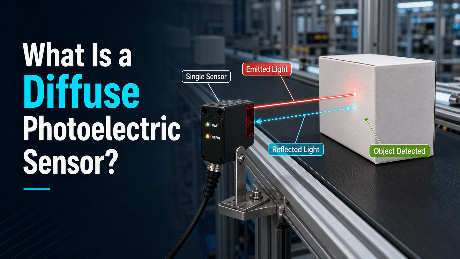
A diffuse photoelectric sensor houses both the light emitter and receiver in a single unit, detecting objects by measuring light that scatters back off the target surface. Typical sensing ranges span 10 mm[1] to 2 meters, depending on target reflectivity—white objects detect farther than black ones. Because it requires only one mounting point and no separate reflector, this design is the cheapest and easiest photoelectric type to install compared to through-beam and retroreflective sensors.
What parts are packed inside the housing? Which specifications matter most when you go to choose one? And how do things like surface color and distance affect whether it detects reliably?
Quick Takeaways
- Emitter and receiver share one housing, requiring only a single mounting point.
- Sensing range spans 10 mm to 2 meters, varying with target reflectivity.
- White objects detect farther than black ones due to higher reflectivity.
- Skip reflectors and second units to cut installation costs versus through-beam sensors.
- Choose background suppression (BGS) models to ignore objects beyond a fixed distance.
What Is a Diffuse Photoelectric Sensor?
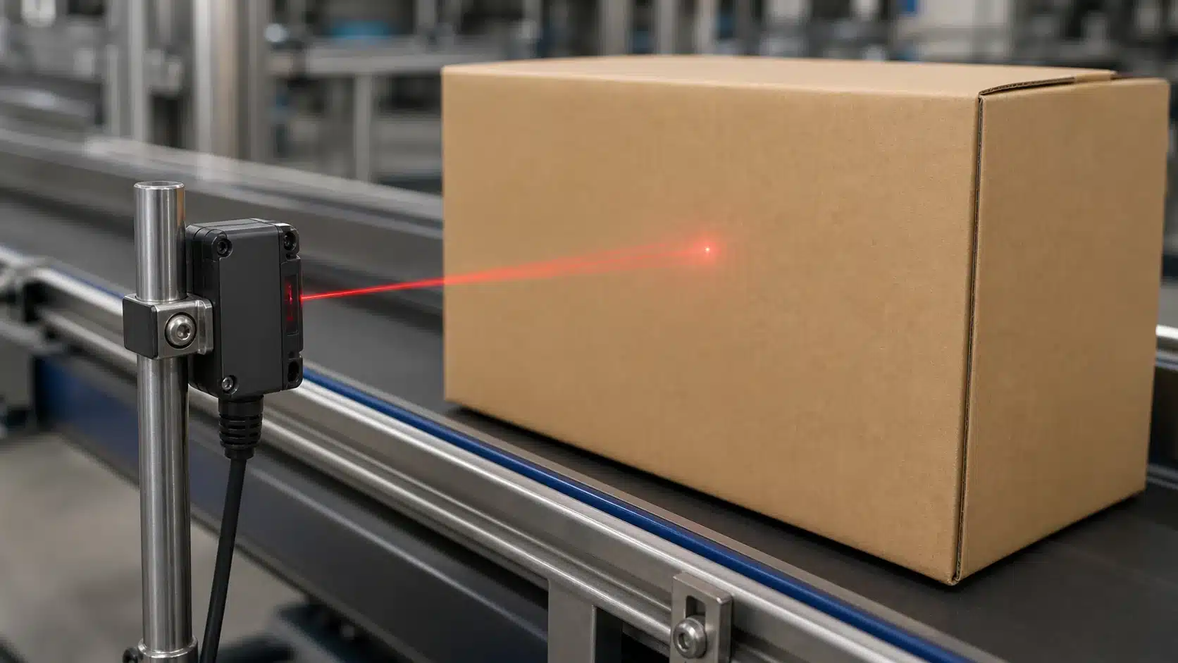
A diffuse photoelectric sensor is basically a single-housing device that sends out a light beam and spots the object directly when that light scatters off the target and bounces back to a receiver sitting inside the same unit. There isn’t a separate reflector or a receiver mounted across from it, so the object itself becomes the “return path” for the light. According to Omron’s 2025 sensing documentation, both the emitter and the receiver share one body, which gives you a single point to mount everything.
This “reflex-off-the-target” idea is really what sets it apart from the other two photoelectric types. A through-beam sensor uses two separate units, an emitter on one side and a receiver on the other, and it triggers when the object blocks the beam between them. A retroreflective sensor uses one housing plus a dedicated reflector, and it triggers when the object breaks the reflected path. The diffuse type skips both of those setups, reading only the diffuse reflection, which is the scattered light coming off a rough or matte surface heading straight back.
That return signal is actually pretty small. A quality diffuse sensor can switch its output reliably when only about 2% of the transmitted light energy comes back from the target, going by ifm’s 2025 specifications. Because detection depends on the target’s surface reflecting light, though, a dark or shiny object cuts down the usable range. Industry data lists typical sensing distances running from a few centimeters up to several meters, depending on the model and how reflective the object happens to be. Keep this dependency in mind when you are picking one out.
How Does a Diffuse Photoelectric Sensor Work?
A diffuse photoelectric sensor works by firing a light beam at a target, then measuring how much of that light bounces straight back to a receiver sitting in the same housing. The output switches when as little as about 2% of the transmitted light energy returns to the receiver (2025), meaning the object itself does the reflecting, no separate mirror needed.
What happens to the signal from emitter to output?
The signal travels through four stages. An LED emitter, usually infrared at 850,950 nm or a visible red beam near 660 nm, sends out pulsed light. When your target passes in front, its surface scatters the light in many directions (that scattering is what “diffuse” means). A tiny fraction lands on the phototransistor receiver, which turns light into a small electrical current.
The amplifier and comparator then take over: the circuit boosts that weak current and compares it against a set threshold value. Above threshold, output turns ON; below it, output stays OFF. Most sensors let you tune this threshold with a potentiometer or a teach button, so you can reject a faint background and lock onto the real part.
Why is the target the reflector, unlike retroreflective types?
Because there’s no dedicated reflector in the setup, the object you want to detect returns the light itself. A retroreflective sensor needs a corner-cube reflector mounted opposite the sensor, and it triggers when an object blocks that mirror. A diffuse type flips the logic: it triggers on the light the object sends back. This one-piece design keeps wiring simple and cuts install points to one, which is why diffuse sensors are the most cost-effective photoelectric option (2025). The trade-off is sensitivity to surface color and shine, which we cover later.
What Are the Main Parts and Signal Flow Inside One?
A diffuse photoelectric sensor contains six core parts working in sequence: an emitter, a receiver, an oscillator, a signal amplifier, a threshold comparator, and an output driver. Light travels from the emitter, bounces off the target, hits the receiver, gets amplified, compared to a set point, then triggers the output. This chain lets the sensor switch reliably even when only about 2% of transmitted light returns (2025).
What does each internal component do?
Each block has one job:
- Emitter: a red or infrared LED that fires the beam. Red (around 660 nm) helps aiming; infrared (around 880 nm) resists dust and dirt better.
- Receiver: a photodiode that converts returned light into a tiny electrical current.
- Oscillator / modulation circuit: pulses the LED on and off thousands of times per second, stamping a signature on the beam.
- Signal amplifier: boosts the weak photodiode current so the logic stage can read it.
- Threshold comparator: decides “object present” or “not present” against a set level.
- Output driver: switches the PNP or NPN transistor that feeds your PLC.
Why does modulated light reject ambient interference?
Modulated light works because the receiver only listens for the exact pulse frequency the oscillator sends. Steady sunlight or overhead LEDs lack that pulse pattern, so the circuit filters them out. This is why a diffuse photoelectric sensor keeps working near bright windows or welding arcs that would blind a simple light detector.
How does the sensitivity potentiometer or teach button set the switching point?
The potentiometer or teach button sets the comparator threshold. Turning the pot raises or lowers how much reflected light counts as “detected.” A teach button samples the live signal, you present the target, press once, and the sensor stores that level automatically, cutting setup errors on the line.
How Do You Calculate Sensing Distance and Excess Gain?
Excess gain is the ratio between the light a diffuse photoelectric sensor actually picks up and the minimum amount it needs before it switches its output. For a sensor to trigger at all, it needs an excess gain of at least 1.0. The trouble is that datasheets rate their range against approximately 90% reflective white paper, essentially a Kodak white card, so your real-world distance starts shrinking the moment your target reflects less light than that reference.
And here is why the spec sheet ends up misleading you. A diffuse photoelectric sensor that is listed at 400mm is quietly assuming that approximately 90%[3] white reference. Excess gain falls off roughly with the square of the distance, and it also scales with how reflective your target happens to be. Some units will switch when as little as 2% of transmitted light comes back, but you really should never design your setup right at that edge.
Here is the worked math for a real target:
| Target | Reflectivity | Effective range |
|---|---|---|
| White paper (reference) | 90% | 400 mm |
| Kraft cardboard | ~40%[4] | ~265 mm |
| Black rubber, angled | ~9% | ~120 mm |
The dark angled part actually loses light in two separate ways. It has low reflectivity, and on top of that its off-axis surface scatters the beam away from the receiver instead of sending it back. That combined loss cuts a 400mm rating down to roughly 120mm[5]. As a general rule of thumb, you should design for an excess gain of 5 to 10 in clean air, and 50 or more in dusty or misty plants, where contamination on the lens quietly steals signal over time. Section 5 explains why black, glossy, and clear targets are the ones that punish you the hardest.
Why Do Black, Glossy, and Transparent Targets Cause Detection Failures?
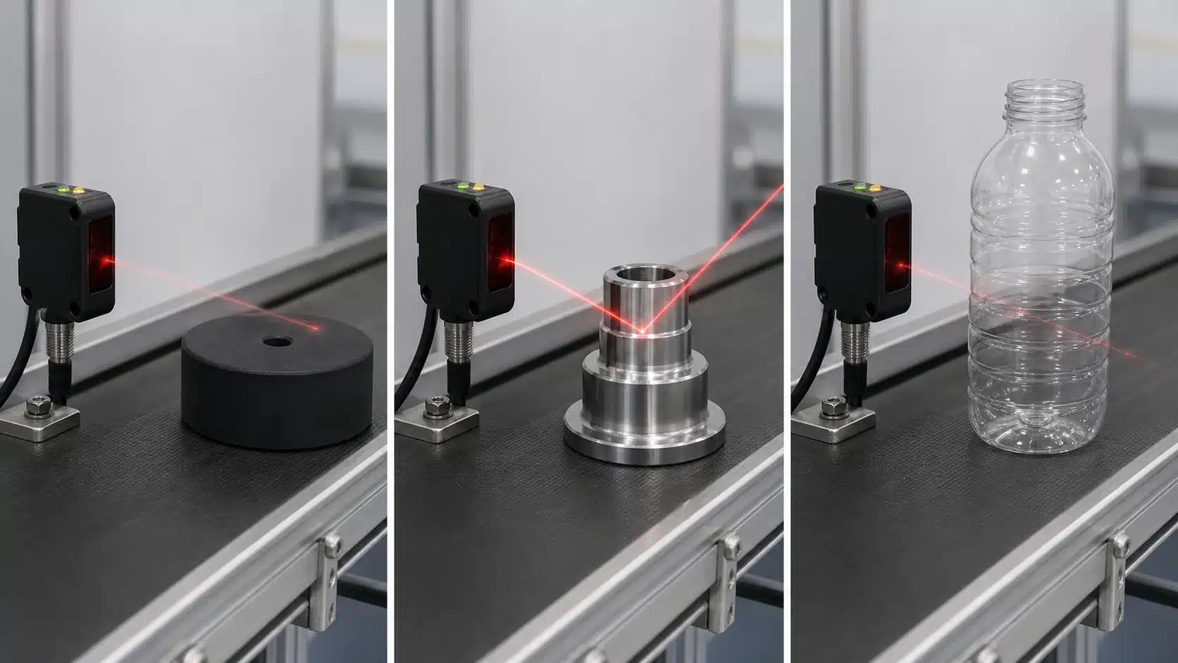
Black, glossy, and clear targets defeat a diffuse photoelectric sensor because each one starves the receiver of returned light. A diffuse sensor only switches when enough light bounces straight back, but matte black returns under 6% of the beam, glossy surfaces mirror it away at an angle, and clear plastics let most light pass through. Industry sensing data confirms that low-reflectivity or transparent targets can slash effective range to a fraction of the rated spec.
⚠️ Common mistake: Setting a diffuse sensor’s range using a white test card, then deploying it against dark targets. This happens because a matte-black object reflects far less light—cutting effective range from 2 meters down to a fraction of that, causing missed detections. The fix: Calibrate against your actual worst-case (darkest) target, or specify a background-suppression (BGS) model that keys on distance instead of reflectivity.
How much range does matte black actually cost you?
A lot. A white sheet of paper reflects roughly 90%[6] of light; flat black rubber reflects around 4,approximately 6%. Since diffuse sensors need excess gain to fire, that drop can cut usable distance by approximately 70% or more. The fix: derate. If a sensor rates 400 mm on white, plan for about 100 mm[7] on matte black, and choose a model with excess gain above 5 at your working distance.
Why do shiny and clear targets need a different trick?
Specular (mirror-like) surfaces bounce the beam away from the receiver unless you tilt the sensor 10,15° off perpendicular. Transparent objects, glass bottles, clear film, barely reflect anything, so a standard diffuse unit misses them. Skip diffuse mode here: use a dedicated clear-object sensor with retroreflective polarized filtering, or a laser diffuse model with tight beam control for color-varying parts.
Diffuse vs Retroreflective vs Through-Beam vs Background Suppression — Which Should You Choose?
Pick through-beam for the longest range and hardest targets, retroreflective for medium range with one wiring point, and a diffuse photoelectric sensor when you can only mount on one side and want the lowest cost. Diffuse types stay the most cost-effective option in 2026 because they need one mounting point and no separate reflector, the direct trade-off is that they give the shortest range of the four.
| Type | Typical range | Alignment effort | False-trigger risk |
|---|---|---|---|
| Diffuse | Few cm to ~2 m | Low | High (background reflects) |
| Background suppression (BGS) | Fixed, up to ~1 m | Low | Very low |
| Retroreflective | Up to ~10 m | Medium | Medium (shiny targets) |
| Through-beam | Up to ~60 m | High (two units) | Very low |
Switch to BGS whenever a bright wall, metal frame, or another conveyor sits right behind your target. BGS uses triangulation (measuring the angle of returning light) to ignore anything past a set distance, so a shiny background stops fooling the sensor, the one weakness the high false-trigger risk of plain diffuse can’t overcome.
Abandon diffuse entirely for clear glass, black rubber below 2% reflectance, or gaps over 3 meters. Those jobs demand through-beam, which reads a blocked beam instead of a reflection. Low-reflectivity targets can cut a standard diffuse sensor’s usable range sharply, don’t fight it.
How Is Background Suppression Different and When Is It Worth It?
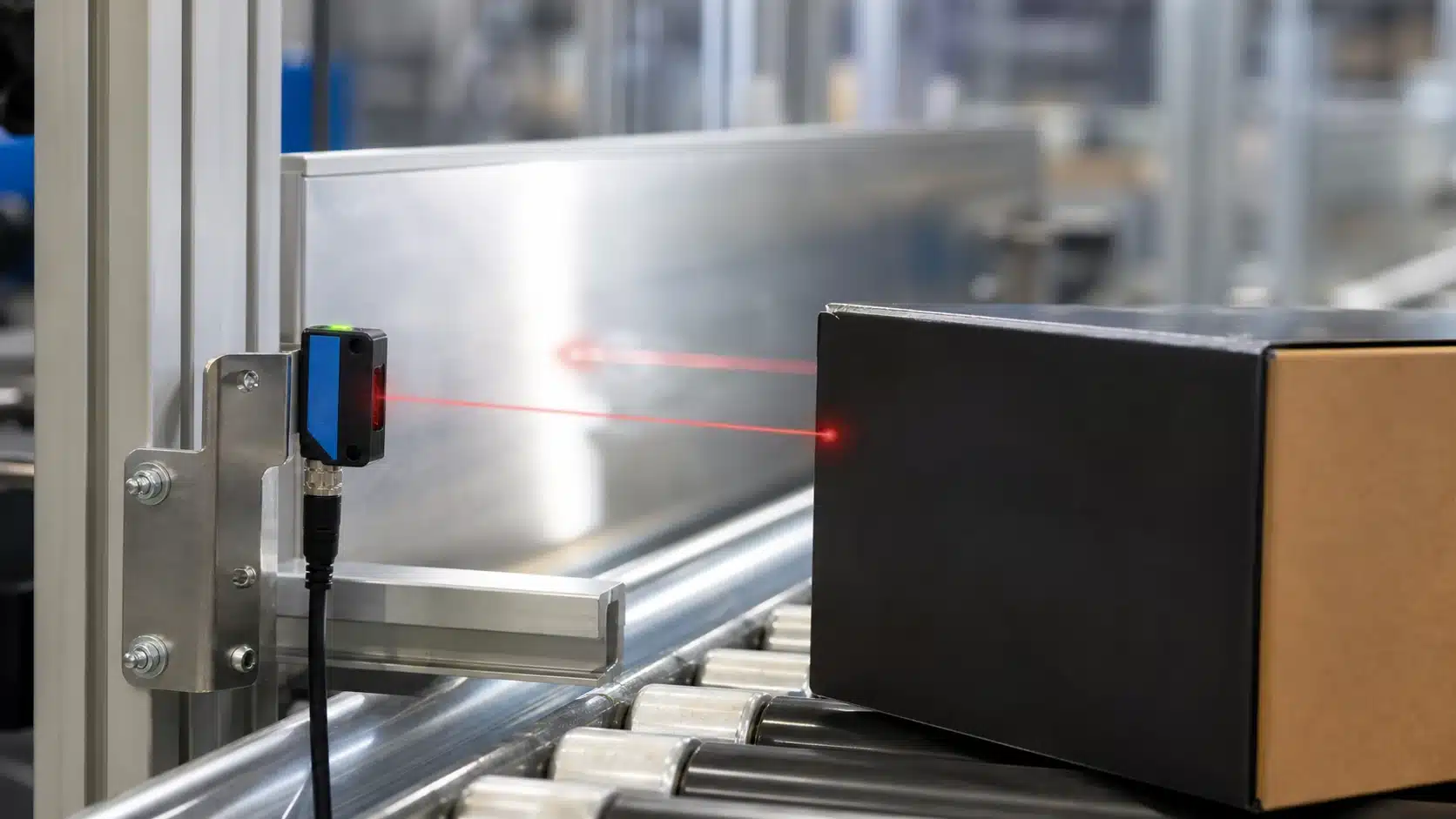
Background suppression (BGS) switches on distance, not reflected brightness. A standard diffuse photoelectric sensor fires when about 2% of transmitted light bounces back, so a shiny wall behind the target can trigger a false detection; BGS ignores that wall. This makes it nearly color-blind, a black box and a white box at the same distance both read as “present.”
How does triangulation make BGS distance-based?
BGS uses triangulation. The reflected beam lands on a position-sensitive receiver (PSD) or a two-element photodiode, and where the light hits tells the sensor the target’s distance, not its color. You set a near/far switch point, and objects past that cutoff, even mirror-bright ones, get rejected.
What edge cases does the near/far cutoff solve?
Two classic problems. On a conveyor, a reflective steel guardrail 300mm behind the belt no longer trips a standard diffuse sensor. In bin-picking, BGS reads only the top parts in a bin and ignores the metal bin floor below. That precise cutoff is why BGS is widely adopted in warehouse automation.
When is the extra cost worth it?
BGS units cost 40,80%[8] more than plain diffuse models and give shorter range, often capped near 300,500mm. Skip BGS if your background is far away or dark. Choose it when targets vary in color, reflectivity shifts batch to batch, or a bright surface sits close behind the object.
How Do You Wire and Integrate a Diffuse Sensor With a PLC?
Match the sensor’s output transistor to your PLC input card: use PNP (sourcing) for sinking inputs and NPN (sinking) for sourcing inputs. A standard 3-wire diffuse photoelectric sensor has brown (+V, usually 24 VDC), blue (0 V), and black (signal). Wire the black signal to a spare PLC input, then confirm output mode before running product.
NPN vs PNP and Light-On vs Dark-On — Which Do You Pick?
PNP outputs are dominant in Europe and modern PLC designs; NPN still appears on older Asian gear. The mode switch also sets logic: Light-On (NO) energizes the output when the target reflects light back, while Dark-On (NC) energizes when the beam is blocked. For box counting on a conveyor, Light-On is standard,each reflected pulse increments the count.
How Do You Fix Chatter, No-Output, and False Triggers?
Three failures cover most field calls:
- Chatter (rapid on/off): excess gain is too low. Boost sensitivity until the margin exceeds 2× the 2% reflected-light threshold, or move the sensor closer.
- No output: check supply voltage at the brown wire under load—a drop below 10 VDC on a 24 V[9] sensor kills switching. Verify load resistance and that you didn’t swap NPN/PNP.
- False triggers: a shiny background is bouncing light back. Lower gain or switch to a background-suppression model.
Always measure voltage while the machine runs, not idle. Voltage sag under a full I/O load is the single most common cause of intermittent faults on diffuse sensors.
Frequently Asked Questions About Diffuse Photoelectric Sensors
Short answers to the five questions buyers ask most before ordering a diffuse photoelectric sensor. Typical sensing ranges run from a few centimeters up to several meters depending on target reflectivity, per Omron’s 2025 product data. Details below.
What’s the typical sensing range?
Most standard diffuse models sense from 20 mm to about 1 meter on a white paper target. High-power versions reach 2 to 3 meters. Cut those numbers by half or more on dark or matte surfaces. Always read the range spec against a 90% reflectance white card, which is the industry reference target.
Can it detect clear objects?
Not reliably. Glass and clear film reflect only about 4% of incident light. A diffuse photoelectric sensor needs at least roughly 2% reflected energy to switch, so clear parts fall right on the edge. Use a retroreflective sensor with polarizing filters instead.
Diffuse vs reflective — what’s the difference?
A diffuse unit reads light bounced off the object itself. A retroreflective (reflective) unit reads light returned from a dedicated reflector, and the object breaks that beam. Reflective sensing reaches farther but needs a second mounting point.
Does target color matter?
Yes, heavily. Black objects absorb light and can shrink range by 60,90%[10]. Test on your actual worst-case part color before committing.
What IP rating do I need for washdown?
Choose IP69K for high-pressure, high-temperature washdown lines. IP67 handles splashes but not steam jets. Verify the rating against the IEC 60529 IP code.
Choosing the Right Sensor for Your Application
Start from your target, not the sensor. Answer two questions first: What is the target made of, and what sits behind it? Those answers decide everything. A matte cardboard box on an open conveyor is easy; a black glossy part 5 mm in front of a shiny steel frame isn’t. Match the sensor to the hard case, never the easy one.
Follow this decision path in order:
- Check target reflectivity. If the surface is dark, clear, or mirror-like, a standard diffuse photoelectric sensor struggles — its range can shrink drastically on low-reflectivity targets, per Banner Engineering.
- Check the background. A close, shiny surface behind the target means you need background suppression (BGS), which triggers on distance instead of brightness.
- Check the range. Long throws or unreliable targets push you to beam-break (through-beam) instead.
Landed on diffuse? Verify the excess-gain margin next. Aim for at least 5x excess gain at your working distance to survive dust and lens film. Diffuse units reliably switch on as little as 2% reflected light, but design with headroom, not the datasheet minimum.
Confirm the output type last. Pick PNP or NPN to match your PLC input card, and choose light-on or dark-on switching for your logic. Diffuse remains the cheapest option, one mounting point, no reflector, which is why its segment is forecast to grow at an 8.9% CAGR through 2032.
Pull the full datasheet excess-gain curves for your exact model, or request application support before you specify. A 20-minute review beats a field return.
See also
Through-Beam vs Retro-Reflective vs Diffuse Photoelectric Sensors
What Is a Photoelectric Sensor and How It Works




