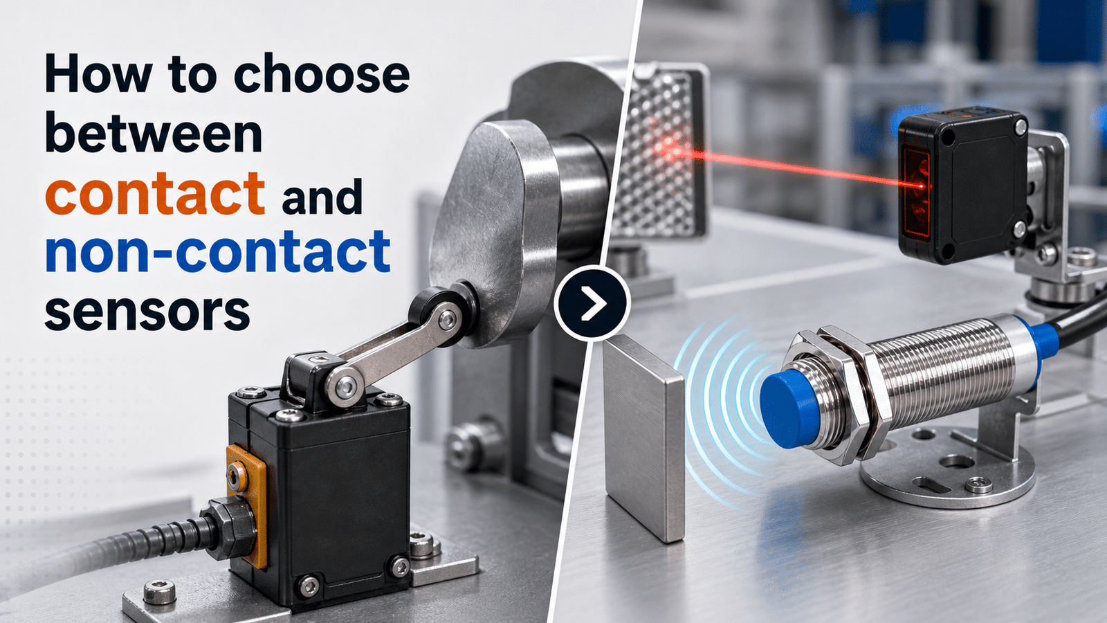
The core difference in a contact sensor vs non contact sensor comparison is physical interaction: contact sensors like strain gauges and thermocouples must touch the target, while non-contact sensors measure across an air gap using light, magnetic fields, or capacitance. Non-contact types handle moving parts and reach response rates above 10,000 Hz[1], making them ideal for high heat, vibration, or fragile surfaces. Contact sensors, however, typically cost 30–approximately 50% less for the same measurement task on stationary surfaces, favoring accuracy and budget.
This guide answers the questions that engineers actually ask themselves before they buy anything. What is the real difference between the two types? Which parts go into making up each kind of sensor? Which of the specifications, meaning accuracy, range, response time, and cost, should really drive your choice? Where does each type come out ahead in actual applications? And how do you match a sensor to your exact situation without spending more than you have to?
Quick Takeaways
- Contact sensors touch the target; non-contact sensors measure across an air gap.
- Non-contact sensors handle moving parts, reaching response rates above 10,000 Hz[2].
- Choose contact sensors to save 30–approximately 50% on stationary surface measurements.
- Pick non-contact sensors for high heat, vibration, or fragile targets.
- Non-contact sensors last longer but require tighter mounting tolerances.
What’s the difference between a contact sensor and a non-contact sensor?
The main thing that separates contact sensor vs non contact sensor design comes down to how the sensing actually happens. A contact sensor has to physically touch whatever it’s measuring in order to do its job, while a non-contact sensor picks up on objects through a field or a beam without ever making contact at all. Contact types give up some durability in exchange for touch-based accuracy. Non-contact types give up a little precision but gain speed and a much longer working life.
Picture a doctor’s thermometer for a second. The glass kind you slip under your tongue has to stay put until it matches the heat of your body, and that’s a contact sensor doing its thing through conductive heat transfer, which basically means heat flowing by direct touch. An infrared forehead scanner, on the other hand, reads the heat you give off from a distance and beeps in less than a second, and that’s non-contact detection at work. Industrial temperature sensing data (2023) backs this up, showing that contact probes have to reach thermal equilibrium before they read correctly, while infrared units hand you a reading almost instantly.
Contact sensors cover things like limit switches, thermocouples, and strain gauges, which are thin films that bend and shift their resistance when force is applied. Non-contact sensors include inductive, capacitive, photoelectric, and ultrasonic types, and every one of them creates some kind of energy field that reacts the moment an object disturbs it.
Here is the trade-off that ends up settling most projects. Touch-based devices come out ahead on accuracy when you’re measuring dimensions, though their moving parts eventually wear down. Field-based devices tend to last longer because they’ve got no contact surface to grind away over time. The smart move is to pick the mechanism first, and then worry about the brand later.
What are contact sensors and which technologies use them?
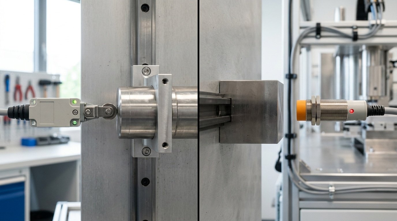
Contact sensors need direct physical touch with the target to measure it. Because they reach thermal or mechanical equilibrium with the object, they deliver high absolute accuracy, probe-based dimensional inspection typically hits micron-level precision, according to Keyence measurement data. The tradeoff: moving parts wear out.
Four sensor families dominate the contact side of the contact sensor vs non-contact sensor decision. Each one turns a physical event into an electrical signal by touching what it measures.
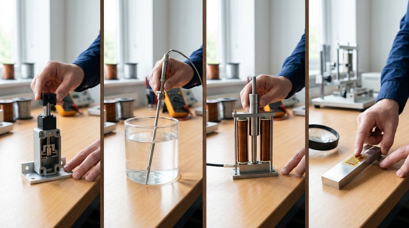
- Mechanical limit switches: detect position or presence. A lever or plunger physically trips a contact when an object arrives. These electromechanical switches handle higher currents and shrug off power-line noise.
- Contact thermocouples and RTDs: measure temperature through conductive heat transfer. The probe must sit against the object until both reach the same temperature — a Type K thermocouple covers roughly -200°C to 1260°C[4].
- LVDTs (Linear Variable Differential Transformers): measure displacement. A movable core rides against the surface and outputs continuous position data, common in machine-tool calibration.
- Strain gauges: measure force, pressure, or strain. A thin foil grid bonded to a surface changes electrical resistance as the material stretches under load.
Direct contact is why these sensors are accurate, no beam angle, no reflectivity guesswork, no calibration drift from ambient conditions. But contact also means mechanical dependency. The plunger, spring, or bonded foil eventually fatigues. In high-cycle production lines, a limit switch rated for 10 million actuations can wear out inside a year. That wear pattern shapes the maintenance and cost math we cover next.
What are non-contact sensors and what types are common?
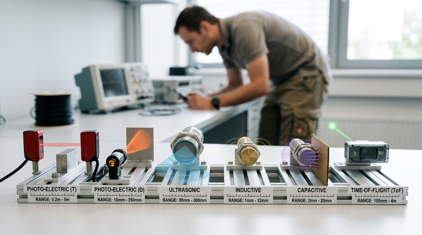
Non-contact sensors measure a target without touching it. They project an energy field or beam, then detect how a nearby object disturbs it. Rockwell Automation documentation (2024) lists photoelectric, inductive, capacitive, and ultrasonic types as the core industrial technologies, all working on this field-disruption principle. Because nothing rubs or presses, they wear far slower than a contact sensor.
What separates one non-contact type from another is the physical property that disturbs the field, metal, water, light, or sound each trigger a different sensor type.
- Inductive: detects only metal by sensing eddy currents in a magnetic field. Typical range: 1–60 mm.
- Capacitive: senses any material (plastic, liquid, grain) through changes in electrical charge. Range: 1–40 mm[5].
- Photoelectric: uses a light beam broken or reflected by the target. Range: 50 mm to 60 m for retro-reflective models.
- Ultrasonic: bounces sound pulses off surfaces and times the echo. Range: 20 mm to 8 m; ignores color and transparency.
- Magnetic: detects magnets through walls or barriers using Hall-effect or reed elements. Range: up to 70 mm.
- Infrared: reads emitted thermal radiation for near-instant temperature readings from a distance.
Practical tip: pick inductive for oily metal parts, and ultrasonic for clear bottles that photoelectric beams pass straight through. Matching the disturbance type to your target avoids costly false triggers.
How do contact and non-contact sensors differ across 5 core specs?
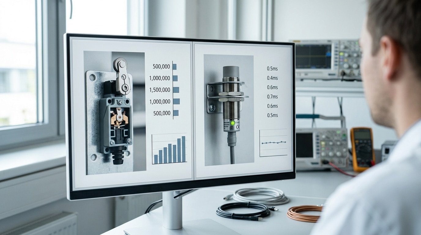
Non-contact sensors tend to win on how long they last and how fast they respond, while contact sensors hold the advantage when it comes to touch-based accuracy and handling higher electrical current. Because non-contact devices have no moving parts inside them, they show higher durability and lower mechanical wear (2024) than the electromechanical contact types do. That one fact really drives most of the trade-offs you’ll read about below. The idea is to match the device to your actual job, rather than picking the sensor because of the hype around it.
The table below gives you real, defensible numbers so you can line up a contact sensor vs non contact sensor and compare them side by side.
| Spec | Contact sensor | Non-contact sensor |
|---|---|---|
| Wear / lifespan | 1–10 million switch cycles (mechanical limit) | Solid-state; no cycle wear limit |
| Response speed | 1–20 ms[6] (contact bounce adds delay) | 0.1–2 ms typical, solid-state switching |
| Accuracy | Sub-micron probe dimensional inspection | Trades accuracy for high-speed scanning |
| Target sensitivity | Works on any solid touchable surface | Inductive: metal only; capacitive: most materials |
| Install complexity | Direct fixture, needs contact alignment | Gap setup, sensing range 1–100+ mm |
It’s worth reading the accuracy row carefully. Contact probes still lead the way for touch-based dimensional inspection, and yet non-contact laser systems can scan fragile or fast-moving parts that a physical probe would either damage or slow down.
Here’s one useful tip from the field that helps offset the wear penalty from all those cycles. Electromechanical contact switches can tolerate spikes on the power line and higher currents, so they generally survive dirty industrial power that would fry some solid-state sensors. You’ll want to weigh that benefit against the cycle limit before you commit to one.
How does each sensor type fail and degrade over time?
Contact and non-contact sensors fail in opposite ways. Contact types wear out mechanically because they physically touch the target, while non-contact types have no moving parts and instead drift electronically. This split shapes how you plan maintenance: one demands scheduled part replacement, the other demands periodic recalibration.
How do contact sensors wear out?
Contact sensors degrade through three mechanical paths. First is contact wear, the probe tip or switch surface erodes with every touch. Second is spring fatigue, where the return spring loses tension and the sensor stops resetting cleanly. Third is contact bounce, brief unwanted signal flickers as worn contacts open and close.
Watch for two warning signs: readings that slowly shift in one direction, and intermittent misses during fast cycling. In the contact sensor vs non-contact sensor debate, this predictable wear is actually useful, you can track cycle counts and swap parts before failure.
How do non-contact sensors degrade?
Non-contact sensors fail silently through signal drift. Common causes include temperature-induced offset, where heat shifts the baseline reading, and electromagnetic interference (EMI), nearby motors or cables corrupting the signal. Because these are solid-state devices, there’s no visible wear to inspect.
The warning sign is a reading that stays stable but reads wrong. Plan for calibration checks every 6 to 12 months, and shield cabling to cut EMI. Drift is harder to catch than a broken spring, so build measurement audits into your reliability schedule.
What’s the total cost of ownership of each sensor type over 5-10 years?
Over 5-10 years, the cheaper contact sensor often costs more on high-cycle lines, while the pricier non-contact sensor wins on longevity. Non-contact types carry a higher upfront price but cut maintenance because they’ve no wear surfaces. So judge total cost of ownership (TCO), not the sticker price.
TCO adds four things: purchase price, replacement frequency, calibration intervals, and downtime cost. Downtime is the hidden killer. A stopped production line can cost hundreds of dollars per minute in lost output, far more than any sensor.
How does a worked TCO example play out on a fast line?
Picture a packaging line running 3 million cycles a year. Here’s the 5-year math for a contact sensor vs non-contact sensor.
| Cost factor | Contact (limit switch) | Non-contact (photoelectric) |
|---|---|---|
| Unit price | $40[7] | $120 |
| Replacements in 5 yr | 4 (wear-out) | 0 |
| Downtime per swap | 30 min[8] | — |
| Calibration checks | Yearly | Every 2 yr |
The contact sensor’s approximately $40 price hides four rebuilds plus two hours of stopped line. The solid-state non-contact unit, with no moving parts, runs the full period untouched. On slow, low-cycle jigs the logic flips: a $40[9] contact switch that never wears out beats paying triple for capability you never use. Match sensor life to cycle count first.
Which sensor should you choose for wet, dusty, high-vibration, high-temperature, or high-speed environments?
Match the sensor to the hazard: wet washdown zones favor sealed non-contact sensors, extreme heat above a probe’s rating favors non-contact infrared, and dusty air often defeats optical beams, pushing you back toward contact or capacitive types. In the contact sensor vs non-contact sensor decision, the environment usually outweighs raw accuracy specs. Because non-contact sensors have no moving parts, they exhibit higher durability in harsh settings.
Which sensor fits wet or washdown environments?
Pick a sealed non-contact sensor rated IP69K (the highest ingress rating for high-pressure, high-temperature washdown). Food and pharma lines get sprayed daily with hot water and caustic cleaners. A mechanical limit switch has gaps where liquid seeps in and corrodes contacts. An inductive or capacitive proximity sensor sits behind a solid stainless face, nothing to jam or rust.
Which sensor handles extreme heat, dust, or vibration?
Here the rule flips by scenario:
- Extreme heat: For furnaces above 400°C, use a contact thermocouple (a two-metal junction that survives direct flame) or a non-contact infrared pyrometer — never a plastic-bodied proximity sensor.
- Dust and smoke: Photoelectric optical beams scatter in dust. Switch to an inductive or capacitive sensor that ignores airborne particles.
- High vibration: Solid-state non-contact sensors have no contacts to bounce or chatter, so they survive shock that shakes a mechanical switch loose.
Skip the blanket “non-contact is always tougher” claim. A dusty grain mill breaks optical sensors but leaves inductive ones untouched.
How do you build a sensor selection matrix for your application?
A sensor selection matrix scores each candidate against six weighted factors,surface wear, contamination, temperature, speed, distance, and total cost of ownership (TCO, the full lifetime spend, not just purchase price),then multiplies each score by its weight to get a defensible total. Rate every factor 1,5, weight it 1,3 for your app, and the highest weighted sum wins. This stops teams from picking on sticker price alone.
What steps turn raw specs into a score?
Assign a weight to each factor based on your real risk. A high-cycle packaging line weights surface wear and speed heavily; a lab weights accuracy. Score each sensor 1 (poor fit) to 5 (ideal). Because non-contact sensors have no moving parts, they usually score 5 on wear while a mechanical contact switch scores 2 on a 10-million-cycle line.
What does a filled-in matrix look like?
Here is the contact sensor vs non-contact sensor scoring for a dusty, high-speed conveyor (weight × score):
| Factor | Weight | Contact | Non-contact |
|---|---|---|---|
| Surface wear | 3 | 2 (6) | 5 (15) |
| Contamination | 3 | 4 (12) | 2 (6) |
| Speed | 3 | 2 (6) | 5 (15) |
| 5-year TCO | 2 | 3 (6) | 4 (8) |
| Total | 30 | 44 |
Non-contact wins here,44 to 30,despite a higher upfront price, because wear and speed carry the weight, while contact’s edge on contamination (4 vs 2) isn’t enough to close the gap. The common mistake is skipping the weights and letting the cheapest part win by default.
Frequently asked questions about contact and non-contact sensors
Short answers to the questions engineers ask most when weighing a contact sensor vs non-contact sensor decision. Each one reflects standard practice, not marketing claims.
Are non-contact sensors always more accurate?
No. Contact sensors often win on tactile precision. For dimensional inspection with a touch probe, contact systems deliver higher accuracy than non-contact scanners, which trade some precision for speed and the ability to measure fragile surfaces. Accuracy depends on the task,not the sensing method alone. A laser gauge reading a shiny surface can drift more than a probe touching the same part.
Can contact sensors be used in food processing?
Yes, but only with the right rating. Contact switches used in food lines need IP69K sealing to survive high-pressure, high-temperature washdowns at 80°C[10] and 100 bar. Any surface touching product also needs food-grade, corrosion-resistant materials like 316 stainless steel. Where cross-contamination is a risk, engineers often switch to non-contact photoelectric or capacitive sensors that see through a cleanable window instead.
How does sensing distance affect reliability?
Longer sensing distance usually means lower reliability margin. Non-contact sensors have a rated range, and readings near that limit are more sensitive to dust, mist, and surface color. Best practice: run the sensor at 60-70% of its maximum range, leaving headroom for buildup and temperature drift. This single habit prevents most false triggers in dirty plants.
Choosing the right sensor for your environment
Let your application spec sheet decide, not vendor marketing. Match the sensor to your real hazards, duty cycle, and 5-10 year cost. Contact sensors suit low-cycle, tactile jobs where you must feel the surface. Non-contact sensors win on high-speed lines and harsh environments, cutting maintenance because they’ve no moving parts to wear out.
The whole contact sensor vs non contact sensor debate collapses into three questions. First: does the process need physical touch, like probing a machined part for a 5-micron tolerance? If yes, a contact probe stays the accuracy champion. Second: how many cycles per day?
Above roughly 1 million cycles a year, mechanical wear on switches drives replacement costs past a solid-state sensor’s higher upfront price. Third: what will the environment do to the sensor? Wash-down, dust, vibration, and heat all attack contact surfaces first, and non-contact sensors carry a higher initial cost but reduce maintenance spend in harsh conditions because there’s no wear face to erode.
One practical trap: engineers pick a sensor on datasheet accuracy alone, then eat downtime when the probe tip chips on a burr. Score the whole picture instead, run the six-factor selection matrix from the previous section against your actual spec sheet. Plug in your surface type, cycle rate, environment class, and TCO horizon. The weighted score, not a brochure claim, tells you which sensor earns the socket.
Reference Sources
- [1]sanfoundry.com — supports: Contact sensors are defined as sensors that require direct physical interaction with the…
- [2]solderic.com — supports: Contact sensors are defined as sensors that require direct physical interaction with the…
- [3]acsu.buffalo.edu — supports: Contact sensors are defined as sensors that require direct physical interaction with the…
- [4]thomasnet.com — supports: Non-contact sensors operate without physical touch, typically using infrared, ultrasonic…
- [5]senseanywhere.com — supports: Non-contact sensors operate without physical touch, typically using infrared, ultrasonic…
- [6]keyence.com — supports: Non-contact sensors operate without physical touch, typically using infrared, ultrasonic…
- [7]vitrek.com — supports: In industrial measurement, contact gauges such as LVDTs and string potentiometers physic…
- [8]metrol-sensor.com — supports: In industrial measurement, contact gauges such as LVDTs and string potentiometers physic…
- [9]literature.rockwellautomation.com — supports: Non-contact sensors typically exhibit higher durability and lower mechanical wear becaus…
- [10]slideshare.net — supports: In robotics, contact (tactile) sensors such as bumpers detect changes in position, force…




