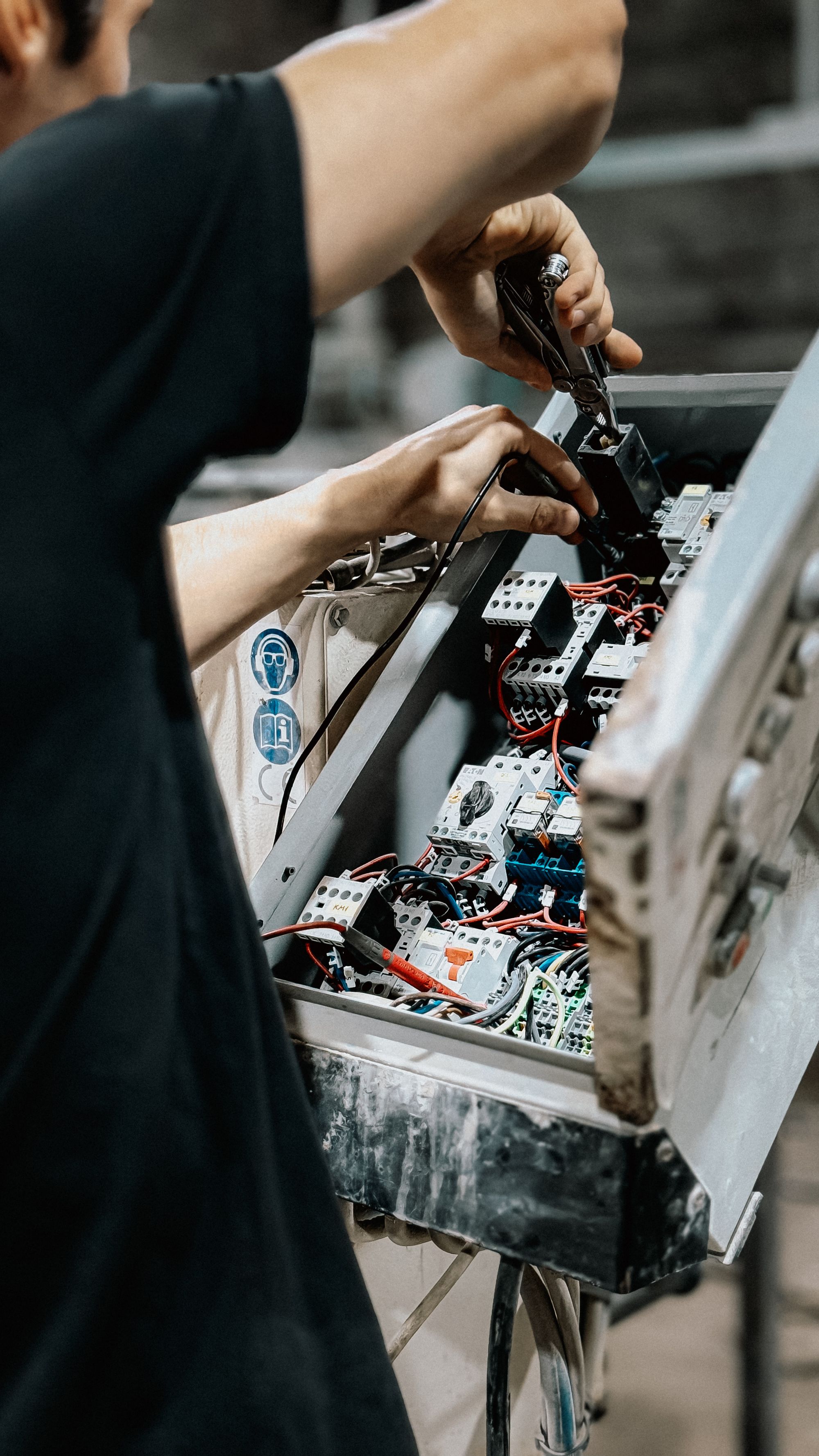
Industrial sensor troubleshooting guide
How Electromagnetic Interference Affects Industrial Sensors and What to Do
EMI can create false switching, analog spikes or offsets, missed counts, communication errors, and controller resets. The reliable fix is to identify the interference source, trace the coupling path, protect the affected signal, and prove the result under the same operating conditions that caused the fault.
- Separate EMI from sensor and wiring faults
- Choose cabling, shielding, grounding, and filtering correctly
- Map the failure to relevant EMC tests
The short answer
Treat sensor EMI as a system problem, not a reason to replace the sensor immediately. Capture when the error occurs, verify power and logic, identify the active noise source, determine whether the disturbance arrives through power, signal wiring, ground, or the surrounding field, then apply the least invasive fix at the source, path, or receiving input. Repeat the original failure condition to confirm the result.
Correlation is a clue, not proof. One controlled change should remove or reduce the suspected coupling path while every other condition stays the same.
Use a system model
Every EMI fault needs a source, a path, a victim, and evidence
The same VFD, relay, or radio can coexist with hundreds of sensors and disturb only one circuit. The difference is usually the coupling path, cable geometry, grounding, input architecture, or installation condition around the affected channel.
Source
VFD edge, motor cable, relay or solenoid switching, welder, power supply, radio, ESD, or surge.
Coupling path
Shared supply or return, capacitive pickup, magnetic induction, shield current, or radiated field.
Victim
Sensor electronics, analog input, PLC digital input, high-speed counter, communication port, or cable.
Evidence
Time correlation, waveform, spectrum, controlled reroute, source suppression, or repeatable immunity test.
Four practical coupling paths
How does electromagnetic interference enter a sensor circuit?
Coupling mechanisms overlap in real machines, but separating them helps choose the right experiment. A filter will not fix poor cable geometry, and rerouting will not remove a transient already entering through a shared 24 V supply.
Conducted coupling
Noise travels on the supply, 0 V, protective bonding network, input, output, or communication conductor. Shared impedances convert switching current into a voltage error seen by other devices.
Capacitive coupling
A rapidly changing voltage couples through stray capacitance into a nearby signal. Long parallel runs, high source impedance, and large voltage edges increase the risk.
Inductive coupling
A changing current links the loop formed by a signal and its return. Large loop area and parallel routing near motor or load current conductors increase the induced voltage.
Radiated coupling
At higher frequencies, cables, seams, and openings can behave as antennas. RF transmitters, switching edges, and poor shield continuity can expose the electronics or attached wiring.
Signal principle is not the same as EMC immunity. An optical sensing element does not respond to a magnetic field in the same way as a Hall element, but the photoelectric sensor's power input, output transistor, processor, connector, and cable can still be disturbed. Evaluate the complete device and installation.
Replace rankings with engineering factors
Which industrial sensor signals are most vulnerable to EMI?
There is no universal ranking by sensor family. Susceptibility depends on signal level, source impedance, cable length and loop area, balance, bandwidth, common-mode range, input thresholds, shielding, grounding, and the immunity design of the exact device.
| Signal architecture | Typical EMI failure | Why it can be vulnerable | Better first-line design |
|---|---|---|---|
| Low-level analog source | Noise, offset, unstable measurement, or saturation | Small useful signal, high gain, high source impedance, or a long unbalanced connection | Condition near the sensor, use a balanced differential path, minimize bandwidth and loop area |
| 0-10 V or other voltage output | Offset, ripple, or incorrect scaling at the PLC | Ground potential difference, shared return impedance, voltage drop, and capacitive pickup | Separate signal and return, use differential or isolated input where appropriate, keep within common-mode limits |
| 4-20 mA current loop | Jumps, dropouts, common-mode fault, or loop power instability | Current transmission is often robust, but the loop is not immune to surge, shared supply noise, excessive common mode, or poor shielding | Use correct loop supply and burden, route as a pair, isolate when ground potentials require it, protect exposed lines |
| 24 V discrete NPN/PNP output | False trigger, missed edge, or rapid chatter | Fast transient crosses the input threshold, 0 V reference moves, or output and PLC input are mismatched | Verify logic and common first, separate wiring, suppress inductive loads, use approved input filtering if timing permits |
| Encoder or pulse output | Extra counts, direction errors, or missing pulses | A narrow coupled transient can be interpreted as a real edge; long high-speed links also depend on impedance and termination | Use the specified cable, differential line driver and receiver, termination, shield connection, and high-speed counter settings |
| Digital sensor communication | Retries, CRC errors, dropouts, or device reset | Digital thresholds provide margin, but timing, common mode, reflections, power integrity, and transient immunity still matter | Follow the bus installation standard, cable and connector rules, topology limits, grounding, and diagnostics |
Do not infer immunity from the words analog, digital, optical, inductive, or smart sensor alone. Compare the complete interface and the declared EMC test conditions.
Look for switching events
Common industrial EMI sources and their timing clues
The event sequence often narrows the search faster than measuring every cable. Record sensor data beside VFD run status, motor starts, relay outputs, valve operation, welding cycles, and machine state.
- VFD and servo systemsErrors appear during enable, acceleration, braking, or speed-dependent operation; motor and brake cables are strong suspects.
- Relays, contactors, solenoidsShort spikes occur at switching, contact bounce, or coil de-energization, especially when suppression is missing or unsuitable.
- Welders and induction loadsFaults follow the process cycle and may affect both signal wiring and the shared supply or bonding network.
- Switching power suppliesNoise can be continuous, load-dependent, or repeated at a converter frequency and its harmonics.
- Radio transmittersSymptoms change with transmitter proximity, antenna orientation, cable position, or radio activity.
- ESD, surge, and poor bondingOne-time resets, latched faults, or damage may follow personnel contact, inductive switching, or an external transient.
Start with the observed symptom
What should you check first when a sensor behaves erratically?
Select the closest symptom. The result does not diagnose the fault by itself; it identifies the evidence to capture and the first coupling paths worth testing.
Choose the symptom
Look for a transient crossing the input threshold
False discrete edges can come from EMI, but also from vibration, target bounce, wrong NPN/PNP or NO/NC logic, a damaged cable, an unstable 0 V reference, or an unsuitable response setting.
Separate common-mode, differential, ground, and process effects
Compare the raw value, input terminals, signal return, loop supply, and source condition. Temperature drift, mechanical vibration, poor calibration, and a failing transducer can resemble electrical noise.
Use the bus diagnostics before changing the sensor
Digital links can report CRC errors, retries, framing errors, timeouts, and topology faults. Check cable type, connector shield, termination, length, device power, and common-mode conditions against the exact bus specification.
Check power integrity and transient protection first
A reset can result from voltage dip, conducted burst, surge, short circuit, loose connector, overloaded supply, watchdog action, or internal fault. Measure at the device during the event, not only at the power supply terminals.
A repeatable field method
Six steps to prove and correct sensor EMI
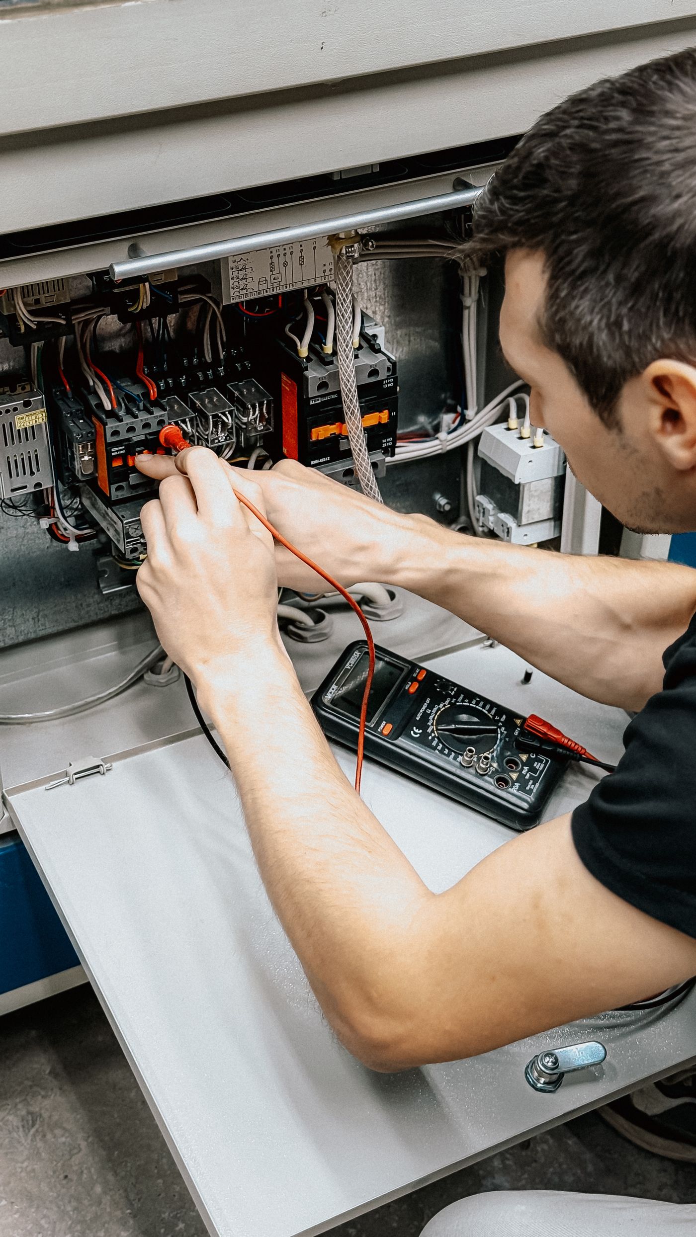
Work under the machine's electrical-safety and commissioning procedures. Controlled tests must not expose personnel, equipment, or the process to hazardous motion or energy.
-
Define the failure in observable terms
Record the exact channel, signal type, normal state, failed state, frequency, duration, machine mode, target condition, and environmental context. Save raw data where possible instead of only a smoothed HMI trend.
Evidence to keepTimestamped sensor output, PLC input, power value, communication status, and machine event.
-
Rule out ordinary sensor and wiring faults
Confirm supply range, connector pinout, NPN/PNP compatibility, NO/NC or light-on/dark-on logic, target distance, alignment, mounting, cable damage, connector seating, PLC common, input threshold, and process timing. EMI should not become a label for every intermittent fault.
Evidence to keepMeasured voltage at the sensor, output state at the sensor and PLC, model settings, and physical inspection.
-
Correlate the fault with a suspected source
Compare error timestamps with VFD enable, motor acceleration, contactor transitions, solenoid release, welding, heater switching, radio activity, and ESD events. Repetition at the same process event raises confidence but does not yet identify the path.
Evidence to keepAn event overlay showing which source is active immediately before and during the sensor error.
-
Change one coupling path at a time
Under an approved test state, temporarily reroute the signal, separate it from one power cable, use a compliant short cable, power the circuit from an appropriate isolated test source, or suppress one inductive load. Keep the target, logic, speed, and remaining wiring unchanged.
Evidence to keepBefore-and-after error rate or waveform with a documented single installation change.
-
Apply the permanent fix in source-path-victim order
Suppress the disturbance near its source where possible, then improve cable zoning, loop geometry, shielding, and bonding. Add filtering, isolation, differential reception, or input conditioning only when the signal bandwidth and device instructions support it.
Evidence to keepUpdated drawing, cable route, shield termination, suppressor or filter part, and final configuration.
-
Recreate the worst event and document the margin
Repeat the operating event that produced the failure, including maximum load, normal cable positions, all nearby emitters, production speed, and realistic target states. Where compliance or high consequence requires it, use the applicable laboratory immunity test and performance criteria.
Evidence to keepFinal error-free run, waveform or log, test conditions, settings, and acceptance criteria.

Reduce coupling before adding filters
Create separate noisy and sensitive EMC zones
Keep motor, drive, brake, and high-current switching conductors out of the sensor and control-signal zone. Use the equipment manufacturer's specified spacing and cable groups. Where separation is not practical, a grounded metal divider or suitable shielded route may be required.
- Route each signal with its return so the loop area stays small; twist the pair when specified.
- Avoid long parallel paths between sensor and power wiring; cross at right angles when a crossing is unavoidable.
- Maintain shield continuity and use the device's intended shield connection hardware.
- Bond cabinet panels, doors, mounting plates, and machine sections as required for high-frequency equipotential bonding.
- Keep suppressors and filters close to the port or load they are intended to protect, following the component instructions.
For example, Siemens gives about 200 mm or a grounded shield plate for particular cabinet zones in its SINAMICS EMC guide. Another drive, cable group, enclosure, voltage, or installation standard may specify a different arrangement.
Noisy zone
VFD and servo drive Motor and brake cables Contactor and solenoid loadsSensitive zone
Sensor and encoder cables Analog and high-speed inputs PLC and communication modulesThe divider represents physical separation, grounded metalwork, or another manufacturer-approved EMC boundary. It does not replace protective earth or product-specific wiring instructions.
A common source of bad advice
Should a sensor cable shield be grounded at one end or both?
Neither answer is universally correct. Shield termination depends on signal type, frequency, cable construction, connector design, common-mode conditions, equipotential bonding, and the equipment manufacturer's EMC concept.
One-end connection may be specified
Some low-frequency analog measurement systems connect the electrostatic shield at the receiving or source reference to prevent low-frequency current caused by different ground potentials from flowing in the shield.
Use only when the measurement-device and cable instructions define this architecture.
Both-end, broad-area bonding may be specified
Drive, encoder, communication, and high-frequency cabinet designs may require continuous shielding connected at both ends over a large surface area, supported by a low-impedance equipotential bonding network.
A long drain-wire pigtail may reduce high-frequency shield performance.
Do not experiment by removing safety bonding
Identify whether the conductor is a cable shield, signal reference, functional earth, or protective earth. Review the sensor, input module, drive, connector, and plant bonding documentation as one system.
Protective earth must never be disconnected as an EMI troubleshooting shortcut.
Layer countermeasures deliberately
Which EMI fixes work at the source, path, and sensor input?
Start where the disturbance is created, then reduce coupling, then harden the receiver. This order often solves multiple affected channels and avoids masking the symptom with excessive filtering.
Reduce the source
- Fit the correct diode, suppressor diode, varistor, or RC network to an inductive load as specified for its voltage and release-time requirements.
- Use the drive manufacturer's motor cable, grounding, line filter, output filter, and installation instructions.
- Repair loose bonding, damaged shields, arcing contacts, and unstable power supplies.
- Minimize high-current switching loop area and keep the return beside its outgoing conductor.
Break the coupling path
- Move sensor and communication cables into the correct cable group, tray, duct, or cabinet zone.
- Shorten unnecessary runs, reduce loop area, twist signal and return, and avoid parallel routing with power conductors.
- Use compatible shielded cable, continuous connectors, metal dividers, or bonded conduit where the system design requires them.
- Separate sensitive 24 V control power from converter or noisy load power when the manufacturer recommends it.
Harden the victim
- Use a balanced differential or isolated input and keep the signal within its common-mode range.
- Condition weak analog signals close to the sensor or use a suitable current-loop transmitter for long industrial runs.
- Select RC, LC, ferrite, or common-mode filtering from the measured disturbance and required signal bandwidth.
- Use input debounce or digital filtering only when it preserves the shortest valid event and does not weaken a safety function.
Adding capacitance, debounce, ferrites, or a low-pass filter without checking source impedance, response time, edge shape, current, voltage, and safety requirements can create missed targets or unstable control. Verify the complete dynamic response after every filter change.
Avoid replacing good hardware
EMI pattern or genuine sensor fault?
No symptom proves EMI by itself. Use the pattern to choose the next measurement and compare it with mechanical, optical, electrical, process, and configuration alternatives.
| Observed pattern | Why EMI is plausible | Other causes to rule out | Decisive next evidence |
|---|---|---|---|
| Error begins with motor acceleration | Drive switching, motor cable current, or shared supply changes at the same event | Mechanical vibration, product movement, voltage sag, PLC sequence, or sensor alignment | Overlay drive state, local sensor supply, raw output, and a controlled cable-route or source-suppression change |
| One-scan false input at relay release | Inductive turn-off transient or contact bounce can create a fast disturbance | Real target bounce, output logic, input filter, loose connector, or program edge logic | Capture coil voltage, sensor output, and PLC input; apply the correct load suppressor and repeat |
| Analog ripple synchronized to machinery | Conducted, capacitive, or inductive coupling can follow the switching cycle | Real process pulsation, vibration sensitivity, aliasing, ground potential, or defective transducer | Compare raw signal and process reference; change sample rate or input baseline only with a documented test method |
| Error changes when cable is moved | Cable geometry changes capacitive, inductive, or radiated coupling | Broken conductor, intermittent connector, mechanical strain, or damaged shield | Continuity and flex inspection plus a compliant alternate route with the same electrical load |
| Fault disappears when a nearby device is off | The device is a candidate source or changes the shared supply and grounding conditions | Process state, vibration, heat, airflow, sequence, or power loading also changed | Reproduce the source transition while holding process and mechanical conditions constant |
| Persistent drift unrelated to switching | Continuous supply noise or ground error remains possible | Temperature, contamination, calibration, target change, aging, or mechanical creep | Compare with a traceable reference, local supply, environmental data, and known-good input simulator |
From field fix to verified immunity
Which EMC tests apply to industrial sensors?
The IEC 61000-4 series defines repeatable immunity test methods for specific disturbance phenomena. These are basic EMC publications. The applicable product, product-family, or system standard determines which tests, ports, levels, configurations, and performance criteria are required.
IEC 60947-5-2 covers several proximity-switch families, including inductive, capacitive, ultrasonic, photoelectric, and non-mechanical magnetic types. IEC 60947-5-7 addresses proximity devices with analog or corresponding digital output. Other measurement and control equipment may fall under IEC 61326-1 or another dedicated standard.

| Reference | Disturbance evaluated | Typical field symptom it can represent | Important limitation |
|---|---|---|---|
| IEC 61000-4-2 | Electrostatic discharge immunity | Reset, false output, latched fault, or communication disruption after personnel or object discharge | The product requirement chooses test levels, points, and performance criteria |
| IEC 61000-4-3 | Radiated RF electromagnetic field immunity | Fault near radios, antennas, or radiated high-frequency sources | It evaluates a defined field setup, not every near-field or cable-coupled condition |
| IEC 61000-4-4 | Electrical fast transient/burst immunity | Rapid switching transients from inductive loads, relays, or contact bounce on connected ports | Coupling method and selected ports must match the applicable equipment requirement |
| IEC 61000-4-5 | Surge immunity | Higher-energy switching or lightning-related overvoltage on power and interconnection lines | It is not a direct-lightning test and does not replace installation surge protection design |
| IEC 61000-4-6 | Conducted disturbances induced by RF fields | RF energy entering through supply, signal, communication, or earth-connected cables | The current edition covers a defined conducted RF range and repeatable injection method |
| IEC 61000-4-8 | Power-frequency magnetic field immunity | Exposure to 50 or 60 Hz magnetic fields near high-current equipment | It does not replace analysis of inductive coupling between field-installed cables |
| IEC 61000-6-2 | Generic immunity for industrial environments | A framework when no relevant dedicated product or product-family standard exists | A dedicated standard takes precedence when one applies |
A compliant component does not guarantee a compliant machine installation. Cabinet zoning, field cabling, grounding, power quality, loads, interfaces, and integration can create a system-level failure outside the component's laboratory configuration.
Field acceptance checklist
Document the evidence before closing an EMI fault
Complete each item under the site's approved safety and commissioning procedures. The goal is a repeatable result another technician can verify later.
Need help separating EMI from the sensor application?
Send XSZ the sensor model, supply and output type, PLC input, cable length and route, shield termination, nearby VFD or switching loads, panel and field photos, event timing, and any waveform or fault log. We can help identify the next decisive check and a more suitable sensor or interface when required.
Continue troubleshooting and selection
Related industrial sensor guides
Use these pages to verify sensor logic, diagnose non-EMI faults, or choose another sensing architecture for the installation.
Frequently asked questions
Industrial sensor EMI FAQ
What is electromagnetic interference in an industrial sensor system?
It is unwanted electromagnetic energy that changes a sensor, cable, input, power supply, communication link, or controller response through conducted, capacitive, inductive, or radiated coupling. The result can be false switching, measurement error, missed counts, communication faults, or resets.
How can I tell EMI from a faulty sensor?
Correlate the fault with a source event, verify ordinary power, logic, target, alignment, cable, and connector causes, then make one controlled change to the suspected coupling path. A fault disappearing when equipment is off is useful evidence, but process, vibration, temperature, and supply loading may also have changed.
Are analog sensors always more susceptible to EMI than digital sensors?
No. Low-level or high-impedance analog signals can be sensitive, but digital links can also suffer false edges, timing errors, common-mode faults, retries, dropouts, and resets. Susceptibility depends on the complete signal architecture, cable, grounding, bandwidth, thresholds, and tested immunity.
Does shielded cable alone stop sensor EMI?
No. The cable must suit the signal and environment, and shield continuity, termination, connector, bonding, routing, source suppression, and input design all matter. A shield cannot correct a noisy shared supply, wrong grounding architecture, or unsuitable sensor interface by itself.
Should the sensor cable shield be grounded at one end or both ends?
Follow the exact sensor, input module, cable, drive, bus, and plant EMC instructions. Some low-frequency measurement systems specify one-end connection to avoid shield current from ground-potential differences. High-frequency industrial systems may specify continuous, both-end, broad-area connections with equipotential bonding. Never disconnect protective earth as a test.
Can a VFD cause proximity sensor false triggering?
Yes, a VFD system can be a source through motor-cable fields, switching transients, shared power, return impedance, or poor bonding. However, verify target movement, vibration, output logic, local supply, and cable condition as well. Diagnose the source and coupling path before replacing the proximity sensor.
Can EMI permanently damage an industrial sensor?
Many disturbances cause temporary errors or self-recovering faults, but ESD, surge, excessive voltage, and high-energy transients can cause latch-up, insulation stress, or permanent input damage. Follow the applicable protection, grounding, and immunity requirements for the installation.
Which IEC standards are relevant to sensor EMC immunity?
Common test methods include IEC 61000-4-2 for ESD, 61000-4-3 for radiated RF, 61000-4-4 for fast transients, 61000-4-5 for surge, 61000-4-6 for conducted RF, and 61000-4-8 for power-frequency magnetic fields. The applicable product or system standard selects tests, levels, ports, and performance criteria.
Should I add debounce or an RC filter to stop false sensor inputs?
Only after identifying the disturbance and confirming the required signal bandwidth. Filtering can remove a false pulse but can also delay a valid edge, miss a small or fast target, change an analog value, or interfere with diagnostics. Suppress the source and improve routing first, then validate the complete response.
Technical references
- Siemens: EMC configuration manual for cable groups, zoning, shielding, bonding, and transient suppression
- OMRON: Photoelectric sensor wiring separation and switching-power-supply precautions
- OMRON: Photoelectric sensor noise paths and countermeasures
- NI: Field wiring, differential measurement, grounding, shielding, and noise coupling
- IEC 61000-4-2:2025 - electrostatic discharge immunity
- IEC 61000-4-3:2020 - radiated RF electromagnetic field immunity
- IEC 61000-4-4:2012 - electrical fast transient/burst immunity
- IEC 61000-4-5:2014 - surge immunity
- IEC 61000-4-6:2023 - conducted disturbances induced by RF fields
- IEC 61000-4-8:2009 - power-frequency magnetic field immunity
- IEC 61000-6-2:2016 - generic immunity for industrial environments
- IEC 60947-5-2:2019 - proximity switches and updated EMC requirements
- IEC 60947-5-7:2024 - proximity devices with analog or corresponding digital output
- IEC 61326-1:2020 - EMC requirements for measurement, control, and laboratory equipment
Industrial photography via Pexels: Bulat843, control-panel installation; Shameer Vayalakkad Hydrose, electrical control room; Bulat843, field diagnosis; Vladimir Srajber, control wiring; and khezez, laboratory testing.