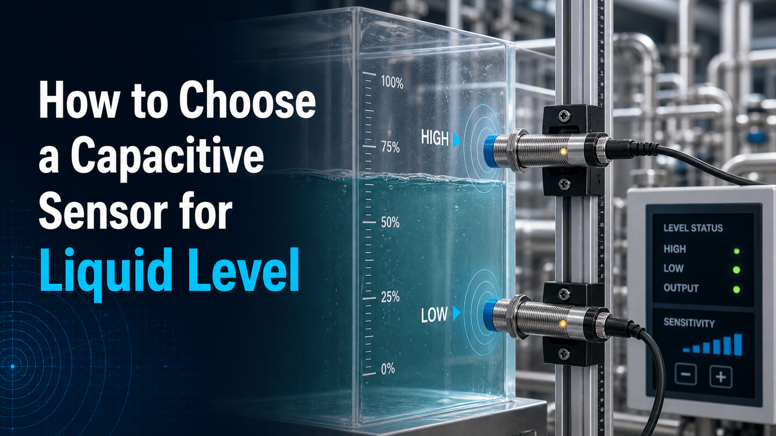
A capacitive sensor for liquid level measures fluid height by detecting changes in capacitance as the liquid rises or falls, requiring no moving parts. Texas Instruments’ TIDU736 reference design pairs a capacitive sensor with an MSP430 microcontroller to monitor water in a non-conductive tank, achieving roughly 3 mm[1] resolution across a 250 mm range (Texas Instruments, 2024). This precision makes capacitive designs ideal for tight-tolerance applications, provided the sensor matches both your fluid type and tank wall material.
To choose the right one, there are a few questions you need to answer first. This guide walks through them: How does a capacitive liquid level sensor actually work? What parts go into making up the sensor? Which specifications matter the most when you’re comparing different models? How does a capacitive design compare against ultrasonic and float sensors? And how much should you plan to budget for it?
Quick Takeaways
- Capacitive sensors achieve ~3 mm resolution across 250 mm[2] in non-conductive tanks.
- No moving parts eliminates mechanical failure points entirely.
- Match sensor to fluid permittivity and tank wall material before buying.
- Choose through-wall setups for tank walls under 6 mm thick.
- Budget approximately $15–$200+ per unit based on IP rating and output.
How does a capacitive sensor measure liquid level?
A capacitive sensor for liquid level actually works by treating the probe and the tank wall as two plates of a capacitor, with the liquid acting as the material sitting between them. As the level rises, the liquid pushes out the air and changes how much charge gets stored. Because water has a relative permittivity somewhere near 80 while air sits at roughly 1, the sensor reads a near-linear capacitance change with water height. That shift is what becomes your level signal.
What actually changes when liquid rises in the tank?
The dielectric constant, which is basically a measure of how well a material stores electrical energy, does all the work here. Air stores almost none of it. Oil stores a little, with a permittivity around 2, and water stores a whole lot. When the liquid covers more of the probe, the measured capacitance climbs, and the electronics turn that into a usable output. Many industrial transmitters map it to a 4,20 mA current signal that tracks with height, so it wires straight into a PLC or process controller.
Why does the liquid’s dielectric constant decide sensitivity?
The bigger the gap between the liquid and the air, the easier it is for the sensor to detect the level. Water’s high value of about 80 produces a strong, clean signal. Oil’s low value of around 2 gives a weak one, so oil setups end up needing higher-gain electronics and careful calibration. A Texas Instruments reference design proved that a capacitive sensor can hit roughly 3 mm resolution over a 250 mm range in a tank that does not conduct electricity. You should always calibrate for the exact fluid being measured, since even the same oil at different temperatures will shift its permittivity.
Which capacitive sensor type fits your tank — probe, point-level, or continuous?
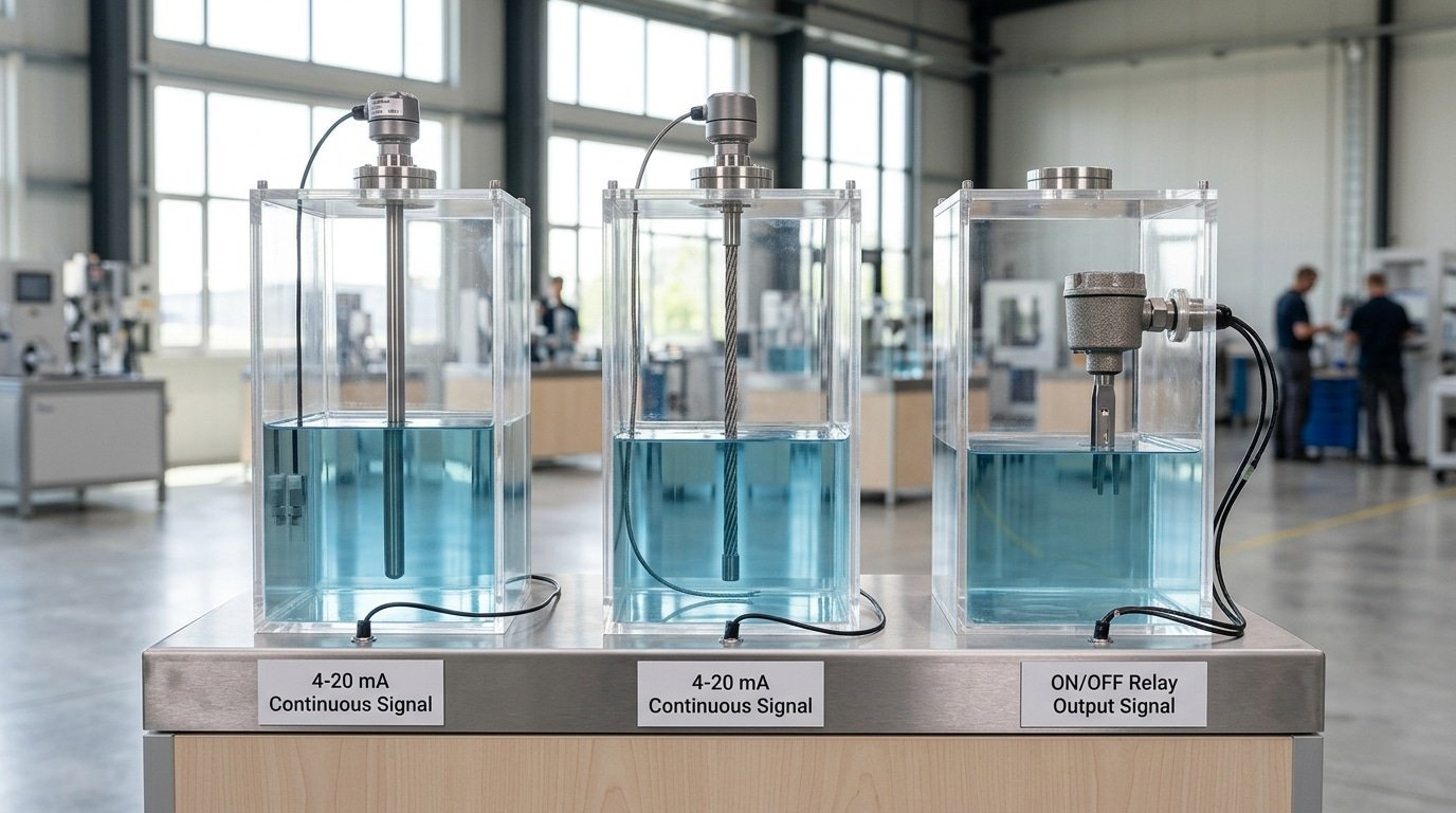
Pick a point-level switch when you only need a high or low alarm, and a continuous transmitter when you need the exact fill height for inventory or process control. Point-level units cost less and wire as a simple on/off switch, while continuous types output a proportional signal like 4,20 mA, mapping level across ranges from roughly 100 mm to over 1000 mm depending on model.
When is a point-level switch enough?
A point-level switch is enough when you just want to stop a pump before overflow or start refilling at empty. It triggers at one fixed spot. Non-contact versions can even sense water through a non-metal wall, some commercial capacitive point sensors detect leakage or overflow externally, so no probe touches the liquid. That protects hygienic tanks and cuts cleaning downtime.
When do you need continuous output?
Choose continuous measurement when you bill by volume, blend recipes, or track stock. A rod or cable probe runs the full tank depth and reports height in real time. Cable probes suit deep tanks over 2 m where a rigid rod would be awkward to install.
- Rod probe: continuous level; rigid stainless or PTFE rod for tanks up to about 4 m.
- Cable probe: continuous level; flexible for deep or tall vessels beyond 4 m.
- Point-level switch: single high/low trip; ideal for pump control and overflow alarms.
A rule of thumb: if operators only ask “is it full or empty?” a switch works. If finance asks “how many liters are left?” you need a continuous capacitive sensor for liquid level.
How do you choose a sensor for conductive vs. non-conductive liquids?
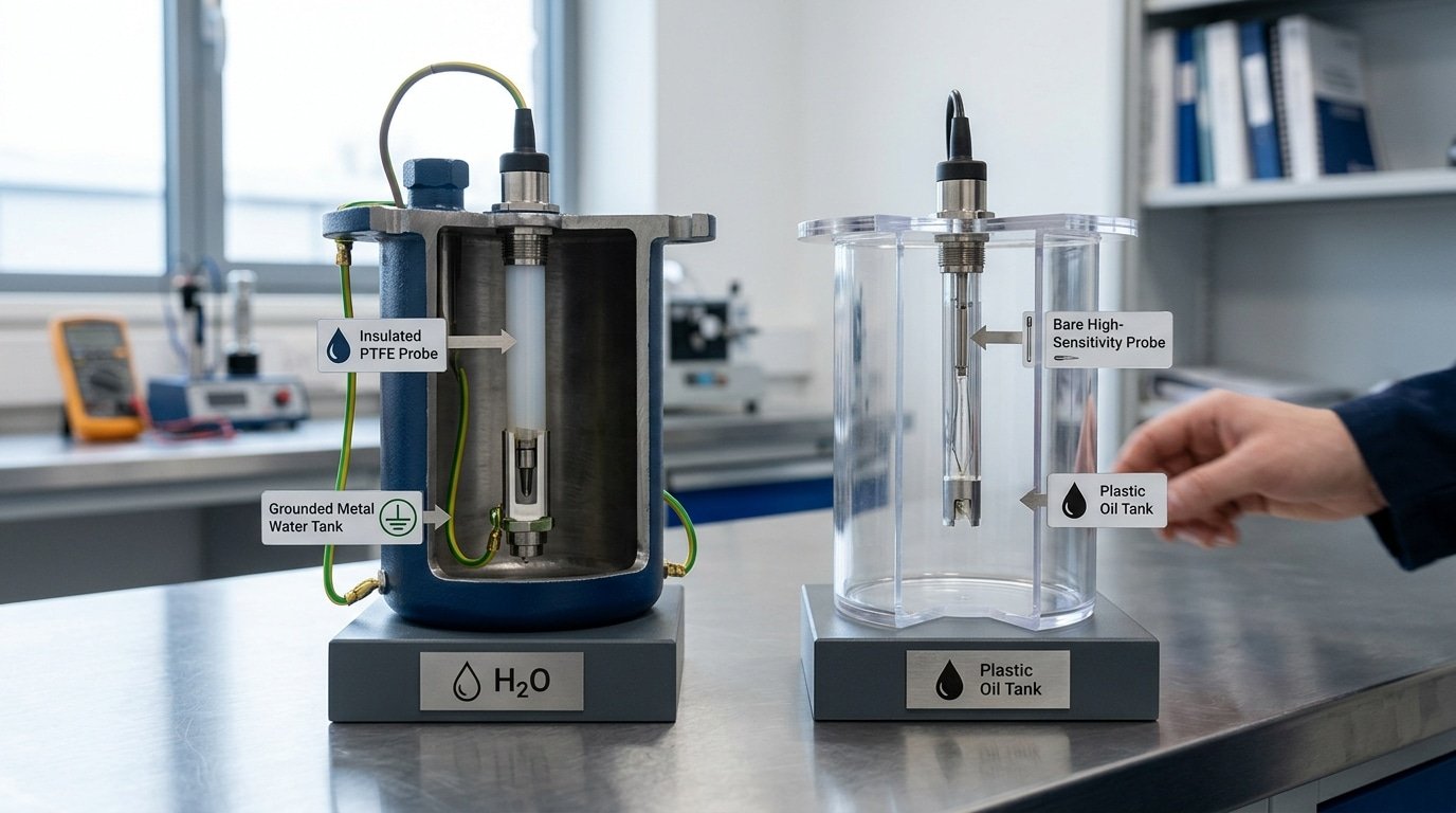
You want to match the probe to how the liquid behaves electrically. Liquids that carry a current, like water and acids, need an Insulated (coated) probe along with a proper ground reference, while liquids that do not carry a current, such as oils and fuels, need a sensor tuned for a low dielectric constant, which basically means the material stores very little electrical charge. Water has a relative permittivity near 80 compared with about 1 for air, according to Wikipedia’s permittivity data, so its large signal swing is easy for the electronics to read, though only when the probe is insulated.
Why do conductive liquids need an insulated probe and grounding?
Conductive liquids let current pass directly between the probe and the tank wall, so a bare metal probe would short out and return meaningless readings. Coating the probe with PFA or PTFE, which are both non-stick plastics that block current, keeps it working as one plate of a capacitor. You also need a solid path back to ground, and that is usually the metal wall of the tank itself. If you skip the ground reference in a plastic tank the readings will drift all over the place, and you can fix this by running a ground reference tube or rod alongside the probe.
Why do non-conductive liquids demand high sensitivity?
Oils and fuels have a permittivity around 2 to 4, which is a tiny fraction of water’s value, so the capacitance change you get per centimeter of rising level is much smaller. A capacitive sensor for liquid level in a fuel tank has to pick out those small shifts, which is why high-resolution front-end electronics, meaning the input circuitry that first reads the signal, really matter here. A Texas Instruments reference design from 2024 reaches roughly 3 mm resolution over a 250 mm range in a non-conductive tank. If you under-spec the electronics, these low-dielectric liquids will give you noisy output that you cannot use.
What sensor works for foaming, viscous, or coating liquids?
When you are dealing with liquids that foam, run thick, or leave a coating behind, the better choice is a capacitive sensor for liquid level that has active buildup compensation along with a smooth rod probe, rather than a plain stainless tip. Foam and film both change the dielectric property right around the probe, so the compensation electronics essentially ignore that thin layer and read only the true surface of the liquid. That approach cuts down on the false-high errors that so often trouble sticky media.
Why does foam trip a false high reading?
Foam sits above the actual liquid, but it still holds enough water to raise the capacitance, and that means a standard probe reads the foam itself as full product. Water’s relative permittivity, which sits near 80, completely dwarfs the value for air near 1 (Wikipedia), so even damp foam nudges the reading upward. The way to fix this is to use a sensor tuned to a switching threshold that ignores light foam density, or a design that instead samples how quickly the capacitance is changing.
How do coating-immune probes handle sticky product?
Sticky media, things like syrup, latex, or oil, tend to leave a film that keeps signaling “wet” long after the actual level has dropped. Coating-immune probes deal with this by using a guard electrode, which is basically a driven shield that measures the film on its own and then subtracts it. This active buildup compensation holds its accuracy even when there is a stubborn 1,2 mm[4] coating clinging to the probe. And the shape of the probe really matters too. You generally want to skip the crevice-prone flush-mount pads when the product is viscous, and instead pick a straight rod with a polished PTFE sheath, so the thick liquid drains away cleanly rather than sticking to it.
What specifications should you compare before buying?
Compare five specs before buying a capacitive sensor for liquid level: temperature/pressure range, accuracy plus repeatability, output type, response time, and supply voltage. Skip vague sensitivity claims. The deal-breakers are the ratings tied to your actual process, a probe rated to 80°C in a 120°C steam line will fail no matter how good its resolution looks.
Which specs are deal-breakers, and which are marketing fluff?
Temperature and pressure range are non-negotiable. Match them to your worst-case process condition, not the average. A CIP (clean-in-place) wash can hit 90°C even if your product runs at 20°C[5].
Accuracy without repeatability is fluff. A sensor that reads ±1% but drifts each cycle is useless for batching, so ask for both numbers. Some lab-grade designs, like the Texas Instruments TIDU736 reference design (2024), hit roughly 3 mm resolution over a 250 mm[6] range, but that assumes stable interface electronics you may not have in a noisy plant.
Which output type should you pick?
Match the output to your controller, not to a spec-sheet buzzword.
| Output | Best for | Note |
|---|---|---|
| 4–20 mA | Continuous level into a PLC | Immune to voltage-drop errors over long cable runs |
| Relay / switch | Point-level high/low alarms | Simplest wiring, no analog input needed |
| IO-Link | Digital diagnostics and remote config | Sends fault data, not just level |
Response time matters for fast-filling tanks, 50 ms beats 500 ms when overflow risk is real. Confirm supply voltage matches your panel (24 V DC is standard). Everything else on the sheet is secondary.
How do you match probe material, IP rating, and hygienic certification to your application?
Match the wetted material to the liquid’s chemistry, the IP rating to the washdown method, and the hygienic certification to the industry. PTFE-coated probes resist acids and fuels, 316L stainless handles most food and water, and ceramic tips survive abrasive slurries. For dairy or pharma tanks, you need 3-A or EHEDG approval, not just food-grade steel.
Which wetted material fits fuel, food, or corrosive tanks?
Pick the material by what the probe actually touches. Fuel and solvents attack cheap plastics, so PTFE (Teflon, a chemical-proof coating) or 316L stainless steel is the safe choice. Strong acids like hydrochloric or hydrofluoric need PTFE-covered probes or ceramic wetted parts. Ceramic also shrugs off abrasive wear from sand-heavy slurries.
- 316L stainless steel: water, milk, oils, mild chemicals — the default for a food-grade capacitive sensor for liquid level.
- PTFE-coated: concentrated acids, fuels, aggressive solvents — coating thickness 0.5–1 mm[7].
- Ceramic (Al₂O₃): abrasive slurries, high-purity chemicals where metal ions can contaminate.
What do IP67, IP69K, and 3-A/EHEDG actually require?
IP67 survives temporary submersion; IP69K adds resistance to 80°C water sprayed at 80,100 bar, the standard for CIP/SIP washdown lines. The IP code (2024) defines both. For sanitary tanks, 3-A and EHEDG certification demand crevice-free surfaces polished below 0.8 µm Ra, so bacteria can’t hide in weld seams.
Skip generic “IP-rated” claims. Ask for the exact IP69K test certificate and the 3-A symbol number before you buy.
Capacitive vs. ultrasonic, float, and conductivity sensors — which should you pick?
Pick a capacitive sensor for liquid level when you need continuous readings on coating, foaming, or non-conductive liquids through a plastic wall. Capacitive tech reaches near-millimeter accuracy, Texas Instruments’ TIDU736 reference design shows roughly 3 mm[8] resolution over a 250 mm range (2024). Ultrasonic, float, and conductivity each win in narrow niches, listed below.
Each method fails somewhere specific. Ultrasonic (which bounces sound off the liquid surface) gets confused by foam and vapor, since a frothy layer scatters the echo. Floats jam on thick, sticky product, think honey or latex, because the moving arm gums up. Conductivity probes only work on liquids that carry current, so they read nothing on oil or fuel.
| Method | Best liquid | Main weakness | Typical price |
|---|---|---|---|
| Capacitive | Coating, foam, non-conductive | Needs calibration per liquid | $100–$600 |
| Ultrasonic | Clean, open tanks | Foam and vapor scatter echo | $150–$800 |
| Float | Clean water, fuel | Jams on viscous product | $20[9]–approximately $150 |
| Conductivity | Water, acids, brine | Blind to oils/fuel | $30–$200 |
The trade-off is simple. Floats cost the least but have moving parts that stick. Ultrasonic gives non-contact continuous data yet dies in foam. Capacitive costs more upfront but survives sticky, foaming, and non-conductive media that break the other three, which is why food, chemical, and pharma plants lean on it.
What are the most common failure modes and false readings to avoid?
The five failures that wreck a capacitive sensor for liquid level are buildup drift, condensation bridging, foam-induced false highs, grounding errors, and temperature-driven dielectric shifts. Since accuracy mainly depends on electrode geometry, dielectric stability, and interface electronics, per a 2014 SAGE review on capacitive level sensors, most errors trace back to something changing at the probe surface.
How do buildup and condensation cause false readings?
Coating and condensation both add capacitance the sensor mistakes for liquid. Sticky product clings to the probe after the level drops, so the reading stays high, while condensation on the upper probe forms a conductive film that bridges the gap. Fix buildup with a Teflon-coated or active-guard probe that ignores the layer. For condensation, mount the electronics head above the tank and add heat tracing to keep the wall warm.
Why do foam and grounding trip alarms?
Foam has a dielectric between air (about 1) and water (about 80), so a thick head can push a point switch high before real liquid arrives. Use a foam-rejection setting or a probe rod that penetrates below the froth. Grounding errors are sneakier: on non-metal tanks, a missing ground reference plate makes readings float. Always bond the reference electrode per the manufacturer wiring diagram.
| Failure mode | Symptom | Field fix |
|---|---|---|
| Coating drift | Reading stuck high | Guard-driven or PTFE probe |
| Condensation bridge | False high near top | Heat trace + raised head |
| Foam false high | Early alarm | Foam-reject firmware |
| Grounding error | Drifting output | Bond reference plate |
| Dielectric shift | Slow error over temp | Temperature compensation |
Temperature changes water’s permittivity, so recalibrate at process temperature, not on the bench. Log a two-point calibration monthly during initial startup.
Frequently asked questions about capacitive liquid level sensors
Buyers ask the same five questions before ordering a capacitive sensor for liquid level: does it touch the liquid, does tank material affect accuracy, can it read through plastic, how often it needs recalibration, and what it costs. Short answers first, then the detail.
Does the sensor need to touch the liquid?
Not always. Non-contact models mount outside the tank wall and read the capacitance change through it. Detection through non-metal walls works because water’s relative permittivity is about 80 versus roughly 1 for air, per published permittivity data. Contact probes stay better for deep tanks or coating fluids.
Do non-metallic tanks work, and does material affect accuracy?
Plastic, glass, and fiberglass tanks all work with external sensing, as long as the wall stays under the sensor’s rated thickness (often 5,10 mm). Wall material shifts the baseline capacitance, so you calibrate to that specific tank. Metal tanks act as the second electrode directly, which simplifies wiring but rules out through-wall mounting.
How often must you recalibrate, and what does it cost?
Recalibrate once yearly for clean water, or every 3,6 months for fluids that leave film or change temperature often. Point-level switches for non-metal walls run roughly $80[10],approximately $300; continuous transmitters with a 4,20 mA output climb to $400,$1,500 depending on range and hygienic certification.
Choosing the right capacitive level sensor with confidence
Start with the liquid, not the sensor. A capacitive sensor for liquid level lives or dies on one number: the liquid’s relative permittivity (dielectric constant, a measure of how well the liquid stores charge). Water sits near 80 while air is close to 1, according to published permittivity data, that big gap is why water levels read cleanly and near-linearly. Oils and solvents sit far lower, so nail your dielectric first, then everything else follows.
Work the path in order. Confirm the dielectric. Pick point-level or continuous. Match probe material and IP rating to the liquid’s chemistry and washdown. Then confirm the failure checklist stays clean:
- Buildup drift: choose active-shield or coating-reject probes for sticky liquids.
- Empty-tank offset: require field calibration, not just factory zero.
- Temperature swing: check the compensation spec across your full range.
- Grounding faults: verify a stable reference against the tank wall.
- Foam or vapor errors: match the probe geometry to the interface you actually have.
Numbers set expectations. A reference design like Texas Instruments’ TIDU736 (2024) hits roughly 3 mm resolution over a 250 mm range through a non-conductive wall, a fair baseline for standard water tanks. Need sharper? Higher-resolution converters push toward sub-millimeter accuracy.
Your next step is concrete. Send a supplier your liquid’s dielectric constant, tank material, temperature and pressure range, and whether you need a switch or a 4,20 mA output. Request a sample to test against real product, or download the selection matrix and score two candidates side by side before you commit.
See also
What Is a Capacitive Sensor and How It Really Works
How Capacitive Sensors Detect Plastic Objects Reliably
PNP sensor wiring diagram with simple step by step guide
NPN vs PNP sensor outputs explained for PLC wiring
Can inductive sensors detect aluminum without losing accuracy




