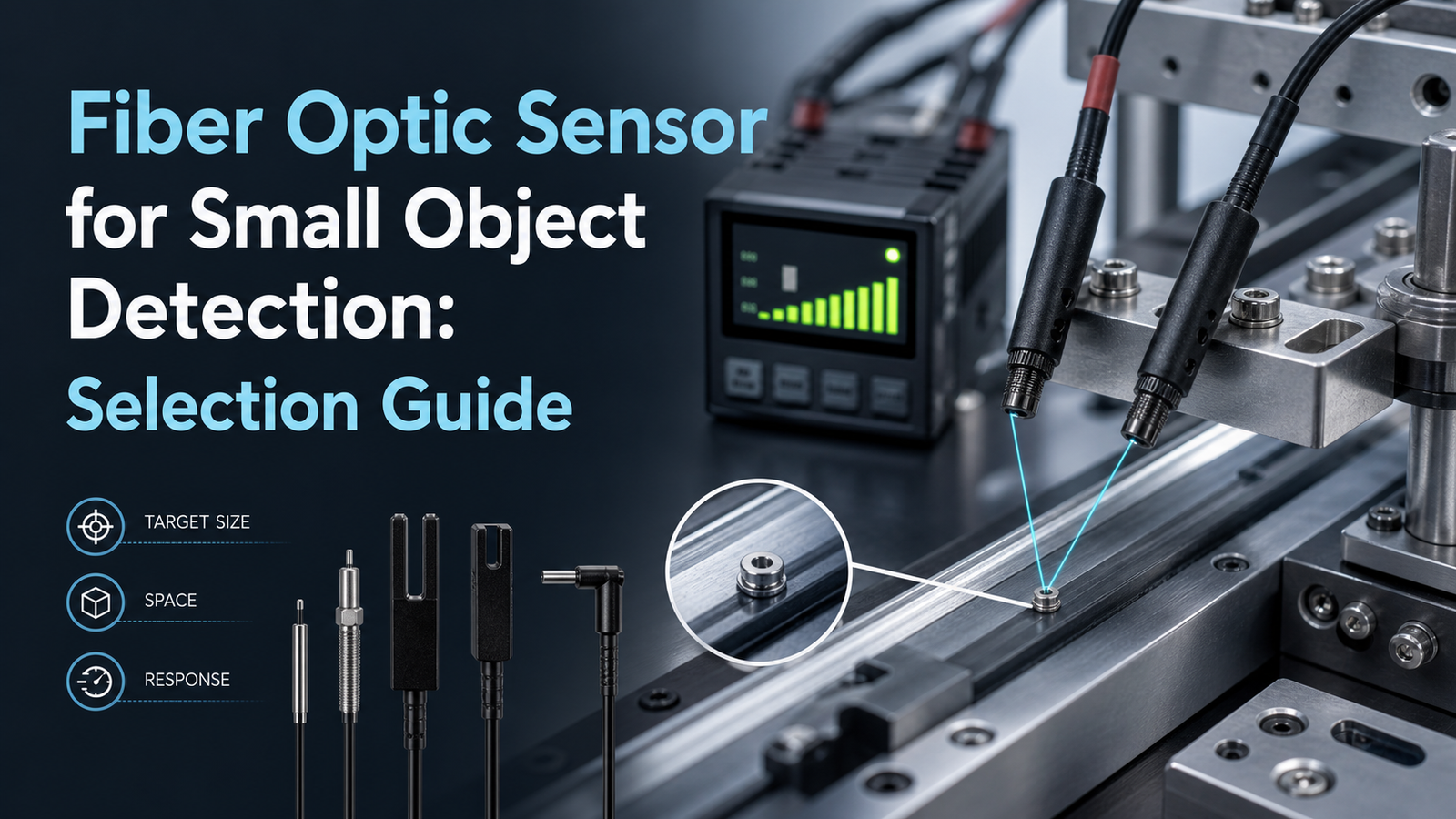
A fiber optic sensor for small object detection channels light through a hair-thin glass or plastic core and registers the beam interruption when a tiny part crosses it, letting the sensor catch objects standard photoelectric units miss. The Optex-FA NF series uses a 0.125 mm[1] fine-core fiber (model NF-DP01) to detect components under 0.5 mm wide, according to Optex-FA (2025). Paired with high-speed amplifiers reaching 25-microsecond response times, these sensors reliably spot rice-grain-sized parts on fast-moving production lines.
This guide answers the questions engineers actually ask. What is a fiber optic sensor, and how does it manage to detect small objects? What parts make up the whole system? How does through-beam sensing differ from reflective sensing? Which specifications, meaning core diameter, beam spot size, and response time, really decide your selection? And what does it actually cost to get one deployed and running?
Quick Takeaways
- Fine-core fibers down to 0.125 mm detect objects under 0.5 mm wide.
- Through-beam mode delivers highest accuracy for tiny transparent parts.
- Choose high-speed amplifiers reaching 25-microsecond response times for fast lines.
- Every system requires fiber cable, amplifier, and stable mounting to function.
- Check beam spot size, not just core diameter, when selecting.
How do fiber optic sensors detect small objects?
A fiber optic sensor for small object detection works by breaking the system into two pieces. There is a fiber amplifier that holds the LED light source and the receiver, and there is a slim fiber head that carries light out to a far-off point. According to 2025 industrial sensor specs, this split lets the tiny head slip into tight machine slots while the electronics sit safely somewhere else. Light travels down the fiber core through total internal reflection, which is basically the same trick that keeps signals moving inside telecom cables, and then it exits as a beam right at the head.
When a part passes through, it changes how much light comes back, and the amplifier reads that little shift.
Through-beam vs. reflective — which principle fits tiny parts?
Through-beam uses two fibers facing each other, so the object actually breaks the beam, and it really wins when you are working with the smallest targets. Reflective, which is also called diffuse, uses a single head that senses light bounced back off the part, and it wins when you can only reach one side of things. A fine-core through-beam setup catches sub-millimeter parts that block even a sliver of light, whereas reflective gives up some of that sensitivity in exchange for one-sided access at short distances.
- Through-beam: This is best for the smallest targets. Fine-core cables of 0.125 mm diameter, per Optex-FA NF-series data (2025), catch sub-millimeter parts that block even a sliver of light coming through.
- Reflective: This works when you can only reach one side. It picks up glossy micro-parts at gaps of 2 mm or less, though weak reflectors do cut into how reliable it stays.
Pick through-beam when you need to catch the tiniest interruption possible. Go with reflective when you have one-sided access and only short distances to cover.
What’s the smallest object a fiber optic sensor can detect?
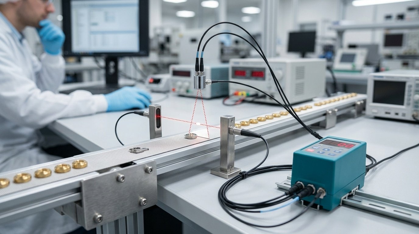
The smallest object a fiber optic sensor can detect is roughly 0.1 mm, limited mostly by the fiber core diameter and beam spot size. Fine-core fibers of 0.125 mm diameter (2025) enable through-beam detection of parts down to a fraction of a millimeter. Bigger cores see bigger targets only.
Think of the fiber core as a flashlight beam. A wide beam spreads light over a large area, so a tiny part passing through blocks too little to register. A narrow beam concentrates the light, so even a 0.1 mm object cuts a measurable slice.
Core size sets the practical floor:
- 0.25 mm core: reliably detects parts near 0.3–0.5 mm[3], common for small-lead components.
- 0.5 mm core: good for 0.5–1 mm objects with generous alignment margin.
- 1 mm core: better for 1 mm and up, but too coarse for micro-parts.
Lensed fiber heads push resolution further. Precision heads reach spot diameters down to 100 µm and resolve height steps under 100 µm (2024), ideal for edge and micro-part sensing in tight spaces.
Here’s the trade-off pros watch closely. A smaller spot raises resolution but shrinks the light budget, the total light reaching the receiver. Less light means less margin against dust, vibration, or slight misalignment. For a stable fiber optic sensor for small object detection setup, size the core just small enough to catch your part, then keep approximately 20% or more excess gain as a safety cushion.
Which specs matter most for detecting tiny parts?
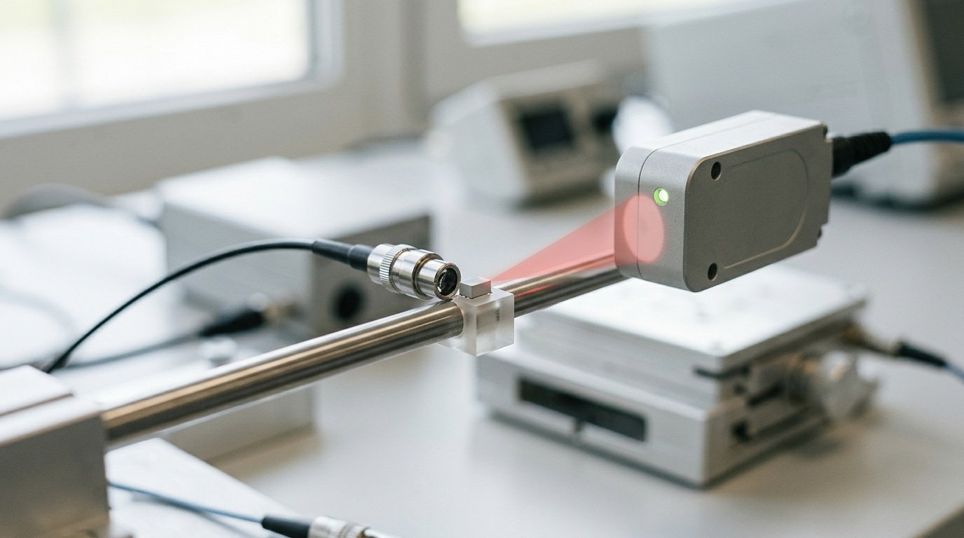
For a fiber optic sensor for small object detection, four specs decide success: response time, excess gain, sensing distance, and beam spot size. On fast lines, response time matters most,a sub-100µs sensor catches parts that a 1ms[4] unit misses. Get any one wrong and detection turns intermittent, dropping parts silently.
Why does response time break high-speed lines?
Response time sets how fast the sensor reacts before a part leaves the beam. A conveyor moving 10 m/s carries a 2 mm part past the beam in just 200 µs. A sensor with 1 ms response reads nothing,the part is long gone. That’s why high-speed fiber arrays reliably catch 2 mm tablets: they combine fast amplifiers with tight fibers. Rule of thumb: response time must be shorter than the part’s dwell time in the beam.
How do excess gain and beam spot decide reliability?
Excess gain is the extra light the sensor receives above the minimum needed to switch. For dependable small-part detection, aim for excess gain of 5,10× at your working distance. Below that, dust or slight vibration causes flicker,the part registers, then doesn’t.
Beam spot geometry must match the target. A 100 µm spot, like the Omron E32 precision heads (2024), resolves height differences under 100 µm. A wide spot on a tiny part blocks too little light,your signal change vanishes into noise.
| Spec | Target value | Failure if wrong |
|---|---|---|
| Response time | <100 µs | Misses parts on 10 m/s line |
| Excess gain | 5–10× | Intermittent switching |
| Beam spot | 100 µm | Signal lost in noise |
How do you detect transparent, glossy, or reflective micro-objects?
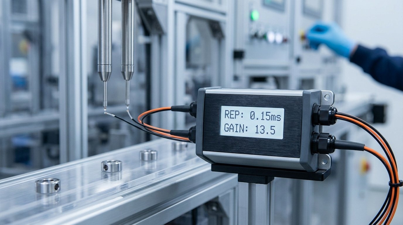
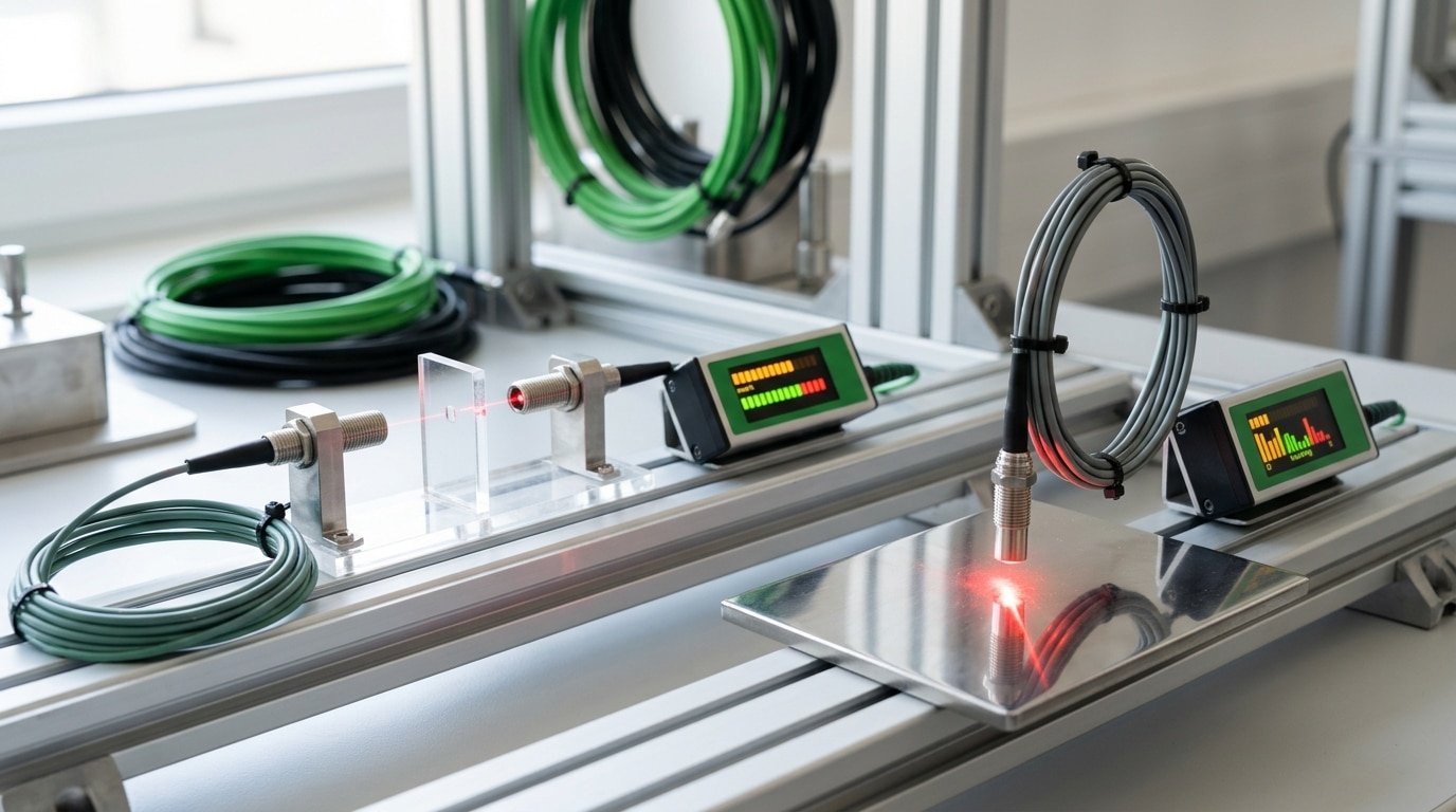
For clear or reflective micro-parts, you’ll want to use through-beam fibers, which some people call opposed-mode fibers. This arrangement sends light from one fiber straight into a receiving fiber on the other side, so it picks up on the small drop in light that happens when an object blocks the beam, rather than reading the surface itself. Even a clear glass part that cuts the beam by just a few percent is enough to trigger a switch. Fine-core cables, like the 0.125 mm-diameter Optex-FA NF series, make this approach dependable for targets that are extremely small.
Why do reflective (diffuse) fibers fail on shiny parts?
Reflective fibers work by bouncing light off the target and then reading whatever comes back. On polished metal or film, though, that surface throws a mirror-like flash straight into the receiver, which is called specular glare, and this causes false triggers even when no part is present. A matte cardboard box sitting behind the sensing zone can actually reflect just as strongly as your actual part does.
What tricks fix glass, film, and polished metal?
- Coaxial fibers: the emitter and the receiver share a single axis, which shrinks the blind spot for close-range parts sitting under 2 mm.
- Retro-reflective mode: you aim at a reflector and detect when it’s blocked, and a polarizing filter rejects the shine coming off glossy parts so that only a real blockage gets counted.
- Threshold teaching: you capture the light level for “part present” and for “part absent,” and then you set the trip point right at the midpoint. Setting a 15–approximately 20%[5] margin above the noise helps it survive vibration.
For transparent film, a fiber optic sensor for small object detection generally works best in through-beam mode with high excess gain, so that even a 3% loss of light reads clearly. It’s better to skip diffuse mode for anything shiny.
How should you mount and align fibers for reliable micro-detection?
Mount fibers rigidly, then focus the beam exactly at the target plane using a lens or focusing sleeve, and adjust until the amplifier shows peak signal. Precision heads offer spot diameters down to 100 µm, per Omron E32 data (2024). At that scale, a 0.1 mm shift can wipe out your entire detection margin.
Tiny spots are unforgiving. When the beam is only 100 µm wide and your part is sub-millimeter, the object must pass through the exact center of that spot. Add a focusing lens or converging sleeve to shrink the beam waist and concentrate light at the pass line, this raises received light and sharpens the on/off edge.
How do you maximize signal on the amplifier?
Set the head, watch the live light value, and move it in tiny steps until the number peaks. A stable setup should show incident light at least 3× your threshold. Less headroom means dust or drift will trigger false readings. Log the peak value so you can spot degradation later.
Why does vibration decouple matter?
Vibration slowly walks a tight beam off-target, so decoupling protects the peak signal you just tuned. Bolt heads to a rigid, machined bracket, not sheet metal that flexes. Route fiber with a slack loop so cable tension can’t drag the head. On a fiber optic sensor for small object detection near motors or conveyors, add rubber isolation mounts to kill micro-oscillation. Never rely on friction alone: use dowel pins or clamped V-blocks so the head returns to the same spot after maintenance.
What common mistakes cause missed small-object detections?
Most missed detections trace back to five field mistakes: over-tight threshold windows, tight fiber bends that leak light, dust on the sensing tip, ambient light bleed, and the wrong fiber type for the target. Each shows up as a flickering or dropped signal. Fix the setup and the signal steadies within one part cycle.
Why does a flickering signal usually point to threshold or bend problems?
A flickering output almost always means your margin is too thin. Set the threshold window too tight and normal light drift trips it on every pass. Widen the window using the amplifier’s two-point teach so the “part” and “no part” levels sit far apart.
Bend radius is the quiet killer. Fine-core fibers like the 0.125 mm-diameter Optex-FA NF series cable lose light fast when kinked below their minimum bend radius. Keep bends gentle. A sharp loop can cut received light by half, dropping you below trigger.
How do dust, ambient light, and fiber mismatch cause dropped signals?
Debris on the sensing tip degrades gain slowly, so detection fails weeks after install. Wipe the tip with a lint-free swab; a light film can cut return light noticeably.
- Ambient light interference: sunlight or LED strobes flood the receiver. Fix it with modulated (pulsed) sensing mode and a shroud over the tip.
- Mismatched fiber type: using diffuse fibers on clear or glossy micro-parts. Switch to through-beam for a stable fiber optic sensor for small object detection.
Fiber optic vs. laser vs. inductive and photoelectric sensors — which is better for small objects?
For most small-object jobs, a fiber optic sensor for small object detection wins on flexibility and head size, but laser sensors beat it on raw precision. Fiber heads shrink to roughly 0.125 mm fine-core diameter (2025), fit tight machines, and see any material. Laser wins when you need sub-100 µm repeatability. Inductive only detects metal. Standard photoelectric lacks the resolution for tiny parts.
Each type trades one strength for another. Pick by what your part is made of, how small it’s, and your budget.
| Sensor type | Min object size | Response speed | Cost (head/unit) | Material limits |
|---|---|---|---|---|
| Fiber optic | ~0.1 mm | 50–250 µs | $50–$200 | Any material |
| Laser (CMOS) | ~0.05 mm[6] | 50–100 µs | $300–$1,200 | Weak on clear glass |
| Inductive | ~1 mm | 0.5–2 ms | $20–$80 | Metal only |
| Standard photoelectric | ~3 mm | 0.5–1 ms[7] | $40–$120 | Any, but low resolution |
Choose laser when you measure exact position or height on a fixed line and can afford the price. Choose inductive only for metal screws or washers in dirty, wet spots where light fails. Skip standard photoelectric for anything under 3 mm. Fiber earns its place when the head must bend into a narrow gap and still catch a 2 mm tablet or a glossy micro-connector.
Which micro-detection scenario should use which fiber setup?
Match the fiber to the failure mode. Parts under 1mm need fine-core through-beam fibers (0.125mm cores exist, per Optex-FA NF-series specs, 2025); high-speed sorting needs sub-1ms[8] amplifiers; transparent film needs opposed-mode; tight mounts need sub-1mm heads. Pick the setup that solves your hardest constraint first.
What setup fits each common scenario?
The table below pairs each scenario with a concrete fiber choice and one spec threshold to check before you buy.
| Scenario | Fiber type | Core/mode | Spec threshold |
|---|---|---|---|
| Parts under 1mm | Through-beam | 0.125mm fine core | Beam spot ≤ 0.5mm |
| High-speed sorting | Diffuse array | Multi-strand bundle | Response ≤ 500µs |
| Transparent film | Opposed-mode | Standard glass fiber | Excess gain ≥ 8x |
| Reflective connectors | Coaxial reflective | Side-view lens head | Spot ≤ 100µm |
| Confined spaces | Compact reflective | Sub-1mm housing | Working distance ≤ 2mm[9] |
How do you pick between two close options?
When two setups both fit, choose the one with more excess gain margin. For glossy or reflective micro-parts sensed at close range, ultra-small reflective heads stably detect features at 2mm or less, even on shiny surfaces. That margin buys you tolerance against dust, drift, and vibration over months of runtime. Precision heads reach 100µm spot diameters and resolve height steps under 100µm, which suits edge and seating checks a fiber optic sensor for small object detection must catch in cramped machine cells.
Frequently asked questions about fiber optic sensors for small object detection
Yes, a fiber optic sensor for small object detection can catch a 0.1 mm wire, read through clear plastic, keep up with fast lines, and stay accurate for years, but only if you match the fiber and clean the tip. Fine-core fibers of 0.125 mm diameter (2025) make sub-millimeter detection real.
Can fiber sensors detect a 0.1 mm wire?
Yes. Use a through-beam (opposed) setup with a fine-core fiber, not a reflective one. A 0.125 mm core focuses the beam tight enough that a 0.1 mm wire blocks a measurable slice of light. Reflective mode struggles here because a thin wire bounces back too little signal.
Do they work through clear plastic?
Sometimes, but expect trouble. Clear plastic passes most light, so the sensor sees little contrast. Switch to through-beam mode and set a tight threshold window, or detect the part edge instead of its face. Glossy plastic reflects unpredictably and causes false trips.
How fast can they detect on a fast line?
Fast fiber amplifiers hit response times near 20,50 microseconds. That means a part moving at 5 meters per second still gives the sensor enough dwell time. On very fast conveyors, pick a “high-speed” amplifier mode and drop any digital filtering that adds delay.
How do you clean the fiber tip?
Wipe the tip with a lint-free swab and isopropyl alcohol weekly in dusty plants. Dust on the face cuts light 10,approximately 20% and slowly shrinks your margin. Never scratch the tip, a scored lens scatters the beam and ruins micro-detection.
Choosing the right fiber optic sensor for your small-part application
Pick your fiber optic sensor for small object detection by starting with target size, not brand. Parts under 1 mm[10] need fine-core through-beam fibers as small as 0.125 mm, like the Optex-FA NF-DP01 core (2025). Match the amplifier to that fiber, then verify on your actual part before buying a full line.
The rule holds across every job: beam spot must be smaller than the part. A 2 mm tablet needs a spot near or below 2 mm. A 0.3 mm wire needs a sub-millimeter focused core. Oversize the beam and the part hides inside it.
Spec priorities, in order: response time (aim under 50 µs for fast lines), excess gain margin, spot diameter, and material handling. For clear, glossy, or reflective micro-parts, default to opposed-mode fibers. Save reflective heads for opaque targets against a stable background.
What should your specification checklist include?
Nail down these before you order:
- Smallest target dimension: the true minimum feature, in millimeters, not the nominal part size.
- Line speed: parts per second, which sets your required response time.
- Fiber mode: through-beam for transparent or shiny parts, reflective for opaque.
- Core and spot size: spot must be smaller than the target feature.
- Environment: confirm humidity and temperature stay within the 35–approximately 85% RH, 0–40 °C range typical for focused-beam fiber cables.
Don’t skip the bench test. Run your real part through a candidate fiber and amplifier, log the excess gain reading, and confirm a stable margin above threshold. A 10-minute sample test catches mistakes that cost hours on a running line.
Send us a sample part. We will pair it with the right fiber and amplifier, verify detection, and share the gain data before you commit to any install.




