
A capacitive sensor detects plastic by sensing changes in an electric field caused by the target’s dielectric constant, requiring no metal contact unlike inductive sensors. Plastic’s dielectric constant (2–4) is lower than water (80), which reduces effective sensing range. Typical sensing distances run 1–30 mm[1] depending on the material and target size. Rated for both metallic and nonmetallic targets, these sensors are ideally suited for detecting bottles, film, powder, and pellets on automated production lines (Eaton, 2025).
This guide answers the questions that engineers actually end up asking. How does the sensing physics work when the target is plastic? How does a capacitive sensor differ from an inductive one? What are the internal parts that make detection possible in the first place? Which specifications, meaning the sensing range, the dielectric constant, and the sensitivity adjustment, decide whether it reads your particular plastic reliably? And what are the real-world mistakes that tend to cause missed detections?
Quick Takeaways
- Capacitive sensors detect electric-field changes, sensing plastic without any metal contact.
- Plastic’s low dielectric constant (2–4) versus water (80) reduces sensing range.
- Expect sensing distances of 1–30 mm based on material and target size.
- Adjust the sensitivity potentiometer to detect thin film or dense pellets.
- Choose capacitive over inductive sensors for nonmetallic targets like bottles and powder.
How Does a Capacitive Sensor Detect Plastic Objects?
A capacitive sensor detects plastic by turning its active face into an electrode, which is basically a surface that reads the electric field sitting in front of it. When a plastic object moves into the sensing zone, the field’s capacitance, meaning how much charge it can hold, shifts because plastics store more charge than air does. That shift trips a circuit inside and flips the sensor’s output to the on position. Industrial models are built for exactly this kind of work, with typical detection distances of a few millimeters for plastic in automation setups.
The physics behind it, in plain terms, works like this. The active face and a ground reference together form a small capacitor. Air fills the gap by default, which gives you a baseline reading. Plastic has a dielectric constant, a number showing how much a material can store electric charge, of roughly 2 to 8, while air sits down at 1. Push some plastic into that gap and the stored charge climbs. The sensor’s oscillator circuit picks up on this jump and switches state within a few milliseconds, once the capacitance crosses the switch point that you set with a potentiometer or a teach button.
The way you mount things actually decides whether that threshold gets crossed reliably. You want to mount the sensor so the plastic passes flush across the face, and not coming in at an angle. An angled approach spreads the field over a smaller area and weakens the signal you get back. Guides on plastic detection point out that a dielectric constant of 2 or higher is enough for reliable triggering.
Why Can Plastic Be Detected Despite Being Non-Metallic?
Plastic gets detected because capacitive sensors respond to any material with a dielectric constant higher than air, not just metals. Air sits at 1.0, while most plastics range from 2 to 8. That difference is enough to shift the sensor’s electric field and cross the trigger point.
The sensor’s active face builds an electrostatic field, like the invisible pull between two charged plates. Air fills that field until an object arrives. When plastic enters, its molecules polarize, the electrons inside shift slightly toward the charge, and this raises the total capacitance the sensor reads.
Dielectric constant is the number that tells you how strongly a material stores that electric energy compared to a vacuum, so a higher number means a bigger field change. A slab of PVC (dielectric near 3) tips the sensor more than dry paper. That’s why a capacitive sensor detects plastic reliably while an inductive sensor sits blind.
Why Can’t Inductive Sensors Do the Same Job?
Inductive sensors only react to conductive metal. They work by generating a magnetic field and sensing eddy currents (tiny swirling currents) that form inside metal targets. Plastic has no free electrons to carry those currents, so it produces zero response.
Capacitive units skip that limitation because they read the dielectric shift instead of magnetic loss, so they handle plastic, glass, wood, liquids, and powders. Field studies since 2018 have confirmed this, using capacitive sensors to identify PE, polystyrene, and transparent plastic packaging as recyclable material. One practical tip: thin, low-density plastics near a dielectric of 2 need higher sensitivity settings, so start calibration there.

What Is the Dielectric Constant of Common Plastics and How Does It Affect Detection Distance?
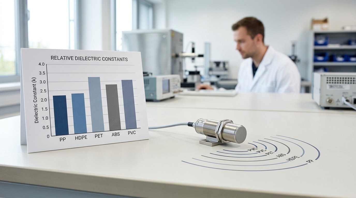
The dielectric constant, which is essentially a measure of how strongly a material responds to an electric field, runs from about 2.2 for polypropylene (PP) up to 4.0 for polyvinyl chloride (PVC) among the common plastics. Most plastics land somewhere between 2 and 8, and this range makes capacitive sensing possible because any value higher than air, which sits at 1.0, will shift the electric field the sensor produces. Higher numbers give the sensor longer reach, so a sheet of PVC will set off the sensor from farther away than a PP tray of the very same size.
The dielectric constant really is the single biggest factor in how far the sensor can reach. When a capacitive sensor detects plastic, the amount the electric field gets distorted grows right along with this value. If you double the permittivity, you roughly double the distance at which the target can sit before the sensor stops noticing it.
| Plastic | Dielectric constant (K) | Relative detection range |
|---|---|---|
| PVC | 3.0–4.0 | Longest, meaning it is the easiest to detect |
| ABS | 2.4–3.8 | Long reach |
| PET | 3.0 | Moderate reach |
| HDPE | 2.3 | Short reach |
| PP | 2.2 | Shortest, meaning it is the hardest to detect |
Here is the practical trap to watch for. Bottles made from PP and HDPE can cut the usable range almost in half compared to PVC. On a sensor rated for 15 mm against a standard target, a thin PP film might only trigger the sensor at around 6.8 mm[3], which is a big drop. What is the fix for that?
You can either turn up the sensitivity potentiometer or choose a sensor with a larger sensing face. The key thing is to never assume the number printed on the datasheet holds true when you are working with low-K plastics.
At What Thickness and Transparency Does Capacitive Detection Start Failing?
Capacitive detection of plastic starts to fail once you get below roughly 1,2 mm of wall thickness for low-dielectric plastics like PE and PP. Below that point, the material pushes aside too little air inside the sensing field to shift the capacitance past the point where it triggers. Transparency really plays no role at all here, since the sensor reads dielectric mass rather than light.
⚠️ Common mistake: Setting the sensitivity potentiometer to maximum to “guarantee” detection of thin plastic film. This happens because engineers assume more sensitivity always helps, but it makes the sensor trip on ambient humidity or nearby machine frames, causing false positives. The fix: tune the pot just above the threshold that reliably reads your target’s low dielectric (2–4), then verify across a full production shift.
Clear plastic gets detected just fine, and that happens because a capacitive sensor detects plastic by measuring how the material changes the electrostatic field between its electrodes, so optical clarity has zero effect on that field. Studies that used capacitance proximity sensors have reliably identified transparent plastic and polystyrene packaging as distinct recyclable materials, which proves that see-through targets are generally no obstacle.
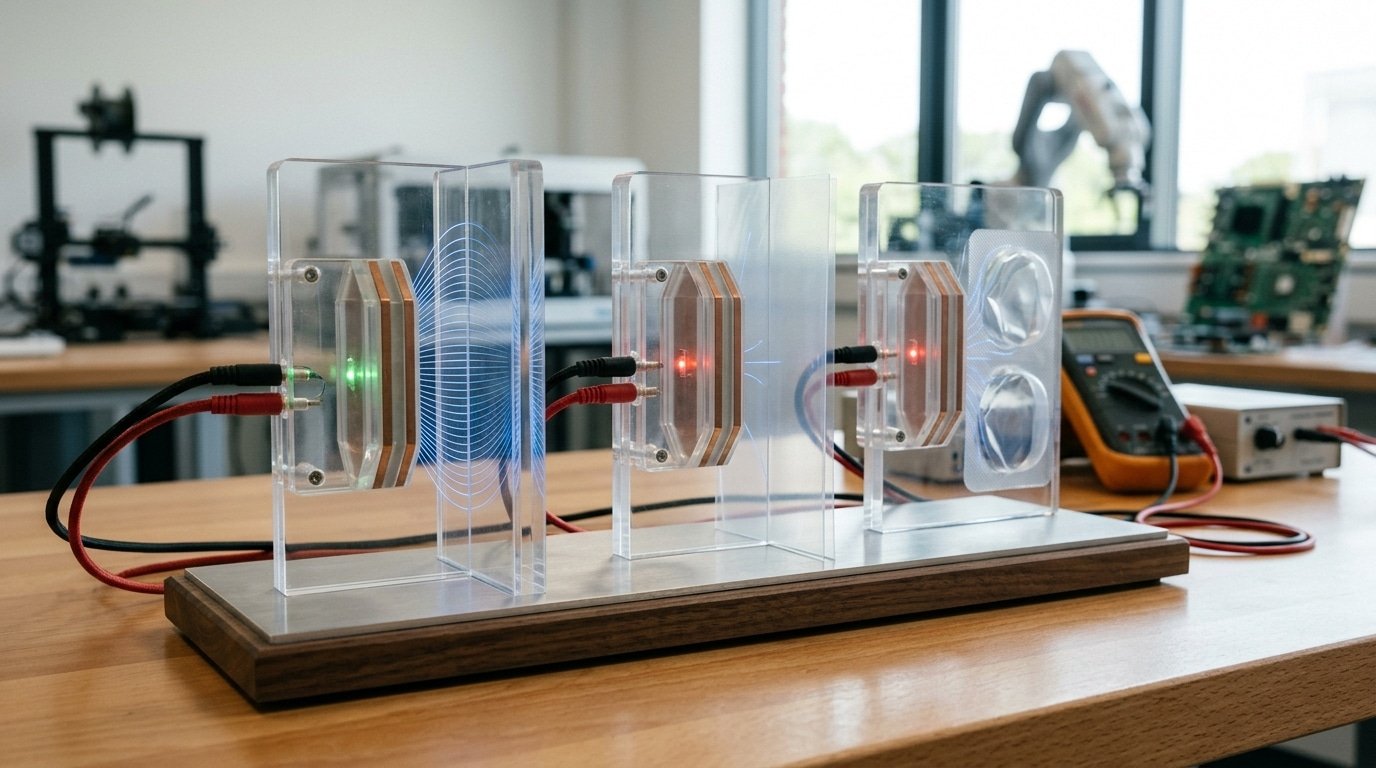
The real limit is dielectric volume, meaning how much high-K material actually sits inside the field. Thin films, foams, and blister packs fail for exactly that reason:
- Thin films (under 0.1 mm[4]): A single plastic film layer barely disturbs the field at all. Detection often needs stacked layers or a backing surface behind it.
- Foams and blister packs: These are mostly trapped air, with a dielectric constant of about 1. The plastic skin is thin, so the effective permittivity stays close to that of air.
- Low-density packaging: An empty blister tray may not trigger the sensor, but the pill or the liquid sitting inside it can.
A practical fix here is to mount the sensor so it detects the contents rather than the wrapper. Capacitive units already sense liquid through thin non-metallic walls, so you can target the denser payload sitting behind the film and raise the sensitivity carefully to avoid noise setting it off.
How Do You Set Up and Calibrate a Capacitive Sensor for Reliable Plastic Detection?
To calibrate a capacitive sensor so it detects plastic reliably, mount it at 50-70% of its rated sensing distance, adjust sensitivity until the target triggers cleanly, then set the switch point above background noise but below the target signal. Most industrial capacitive sensors detect nonmetallic targets like plastic at a few millimeters in typical use, so precise gap control matters.
How Do You Set the Mounting Distance and Sensitivity?
Fix the gap first, then tune sensitivity. Mount the active face so the target sits at roughly two-thirds of the rated range. This leaves headroom for vibration and part-to-part variation. Use one of two adjustment methods:
- Potentiometer (multi-turn screw): Turn it up until the target triggers, then back off until it just drops out. The stable window sits between those two points.
- Teach-in (push-button): Present an empty zone, press once to record background, then present the plastic part and press again. The sensor calculates the midpoint threshold automatically.
How Do You Set the Threshold Above Noise?
Aim the switch point roughly halfway between the empty-field reading and the plastic-present reading. If the background reads 40 counts and the plastic reads 90, set the threshold near 65. That gap,called hysteresis,stops the output from chattering when the part barely moves. Thin or low-dielectric plastics shrink this gap, so raise sensitivity carefully rather than maxing it out.
How Do You Verify Repeatability?
Run the same part through the sensing zone 20 times at slightly different positions and offsets. Reliable detection means every pass triggers, with no false trips on an empty conveyor. Test at both temperature extremes your line sees; a capacitive sensor that detects plastic at 20°C can drift as humidity and heat shift the dielectric field. Log the trigger margin and re-check after 24 hours[5] of production.
Why Does the Sensor False-Trigger and How Do You Fix It?
Capacitive sensors false-trigger mainly from three causes: moisture on the active face, metal or fixtures inside the sensing zone, and loose mounting. Because these sensors respond to any dielectric shift, and water has a relative dielectric constant near 80, far above the 2,8 range of most plastics, even a thin condensation film can read like a solid target. Fix it by tuning hysteresis, shielding, and cutting sensitivity.
How Do Humidity and Condensation Trip the Sensor?
Humidity trips the sensor because water vapor and surface condensation raise the ambient capacitance the sensor reads at rest. On a cold morning line running below the dew point, a wet face mimics the exact dielectric change a plastic part causes.
The practical fix is hysteresis tuning, widening the gap between the switch-on and switch-off thresholds so a small moisture drift can’t toggle the output. Set hysteresis to 15,approximately 20% of the nominal sensing distance and route dry compressed air across the face on chilled environments.
Why Does Nearby Metal Cause False Signals?
Background metal false-triggers because conductive fixtures within range act like a permanent target, inflating the baseline. A stainless bracket 8 mm[6] behind a sensor with a 10 mm range will hold the output permanently on. Three countermeasures address it:
- Guard electrode: a driven shield ring around the active electrode that cancels side and rear fields, focusing detection forward.
- Reduce sensitivity: back off the potentiometer until the fixture drops out but the plastic still registers.
- Non-metallic mounting: swap steel brackets for POM or PVC blocks within the sensing cone.
Does Loose Mounting Really Matter?
Yes, an unstable mount lets vibration change the sensor-to-target gap by fractions of a millimeter, and that shift alone flips the reading near the threshold. Torque the locknuts to spec, add a jam nut, and verify the capacitive sensor detects plastic consistently across 50 cycles before running production.
When Should You Use Photoelectric or Ultrasonic Sensors Instead of Capacitive?
Use a capacitive sensor for near-contact detection of solid or bulk plastic within a few millimeters. Switch to ultrasonic for clear films, thin sheets, or ranges beyond that reach, and pick photoelectric for fast-moving opaque parts. Capacitive proximity sensors are recommended for plastic, glass, and wood with typical distances of only a few millimeters, so range is the first thing that rules them out.
The choice comes down to three questions: how far away is the target, what’s it made of, and how messy is the environment? A capacitive sensor detects plastic well when it sits close and the part is thick enough to shift the electric field, but it struggles with fine films and long gaps. Ultrasonic sensors ignore color and transparency because they read sound echoes, not dielectric change,perfect for glossy PET or clear wrap. Photoelectric sensors trip in under 1 millisecond, so they suit conveyor lines running hundreds of opaque bottles per minute.
Which sensor fits your range, target, and environment?
Match your job to the row below. Each type wins in a clear zone; overlap is small.
| Condition | Range | Best target | Environment |
|---|---|---|---|
| Capacitive | 0–20 mm[7] | Solid/bulk plastic ≥1–2 mm thick | Dry, stable, low dust |
| Ultrasonic | 30 mm–6 m | Clear film, thin sheet, liquids | Tolerates fog, color, transparency |
| Photoelectric | 10 mm[8]–30 m | Opaque parts, fast lines | Sensitive to dust on lens |
If-then rule: If the plastic is transparent film under 0.5 mm, then use ultrasonic. If parts race by faster than 1,000 per minute, then use photoelectric. If you need contactless bulk sensing under 20 mm[9] in a dry cell, capacitive stays the cheapest and simplest pick.
Frequently Asked Questions About Capacitive Sensing of Plastic
Yes, a capacitive sensor detects plastic through thin container walls, sees the difference between empty and filled bottles, and works across most colors. Typical sensing ranges for plastic in industrial use sit at just a few millimeters, depending on the sensor’s design and the plastic’s dielectric constant.
Can a capacitive sensor detect plastic through container walls?
Yes. Capacitive proximity sensors read changes in capacitance through thin non-metallic walls, which lets them detect liquid levels inside plastic or glass containers without direct contact. Keep the wall under about 4 mm and dial up sensitivity. Thicker walls eat into your effective range fast.
Does it tell empty from filled bottles?
It does. An empty PET bottle presents mostly air (dielectric constant near 1), while a water-filled bottle jumps to roughly 80. That huge gap makes filled bottles trigger at a longer distance. Set your threshold between the two capacitance readings, and the sensor flags fill state on the line.
Does plastic color affect detection?
Color barely matters. Capacitive sensing responds to dielectric constant, not surface reflection or opacity. A black PVC part and a clear PVC part with the same thickness read almost identically. This is why capacitive beats photoelectric for dark or transparent plastics that scatter light.
What’s the typical sensing range in millimeters?
Most industrial capacitive sensors detect plastic from 2 mm to 25 mm, sized to the sensor face diameter. High-dielectric plastics like PVC (around 3) reach the longer end; low-dielectric films sit near the short end. Bigger sensor heads push range further but pick up more background noise.
Choosing the Right Sensor for Reliable Plastic Detection
Before you buy a capacitive sensor that detects plastic, test your actual sample against three numbers: the plastic’s dielectric constant (most sit between roughly 2 and 8, per sensor manufacturer data), its wall thickness, and the working gap you need. If your part scores low on all three, a capacitive solution will struggle, pick a different technology.
Run through this checklist with the exact plastic you plan to detect, not a datasheet stand-in:
- Dielectric constant ≥ 2: Confirm your polymer clears the threshold that lets an electrostatic field register the target. PVC (about 3) and nylon (about 4) detect easily; thin PP or PE films near the low end need a high-sensitivity model.
- Solid mass over thin film: A 5 mm[10] plastic block reads far more reliably than a 0.3 mm sheet. Below 1–2 mm, expect trouble and test it physically first.
- Sensing gap under a few millimeters: Standard industrial capacitive units give detection distances of a few millimeters for plastic. Need more range? Larger active faces buy you distance but widen the field.
- Adjustable sensitivity potentiometer: Insist on it. You will fine-tune the trigger point against your real sample, not a factory default.
Bench-test before committing. Mount the sensor, place your plastic part at the intended gap, then turn sensitivity down until it just triggers, that margin protects against drift from temperature and humidity. Verify with 20 to 30 repeat passes; a stable switch point every time means the choice holds. For liquid-in-container jobs, confirm the wall is non-metallic and thin enough for the field to reach through. Do this validation and your capacitive sensor detects plastic consistently on the line, not just on the spec sheet.
See also
Can inductive sensors detect aluminum without losing accuracy
What Is a Capacitive Sensor and How It Really Works
What Is a Photoelectric Sensor and How It Works
Slot Sensor for Small Part Detection: Fixed Gap Applications




