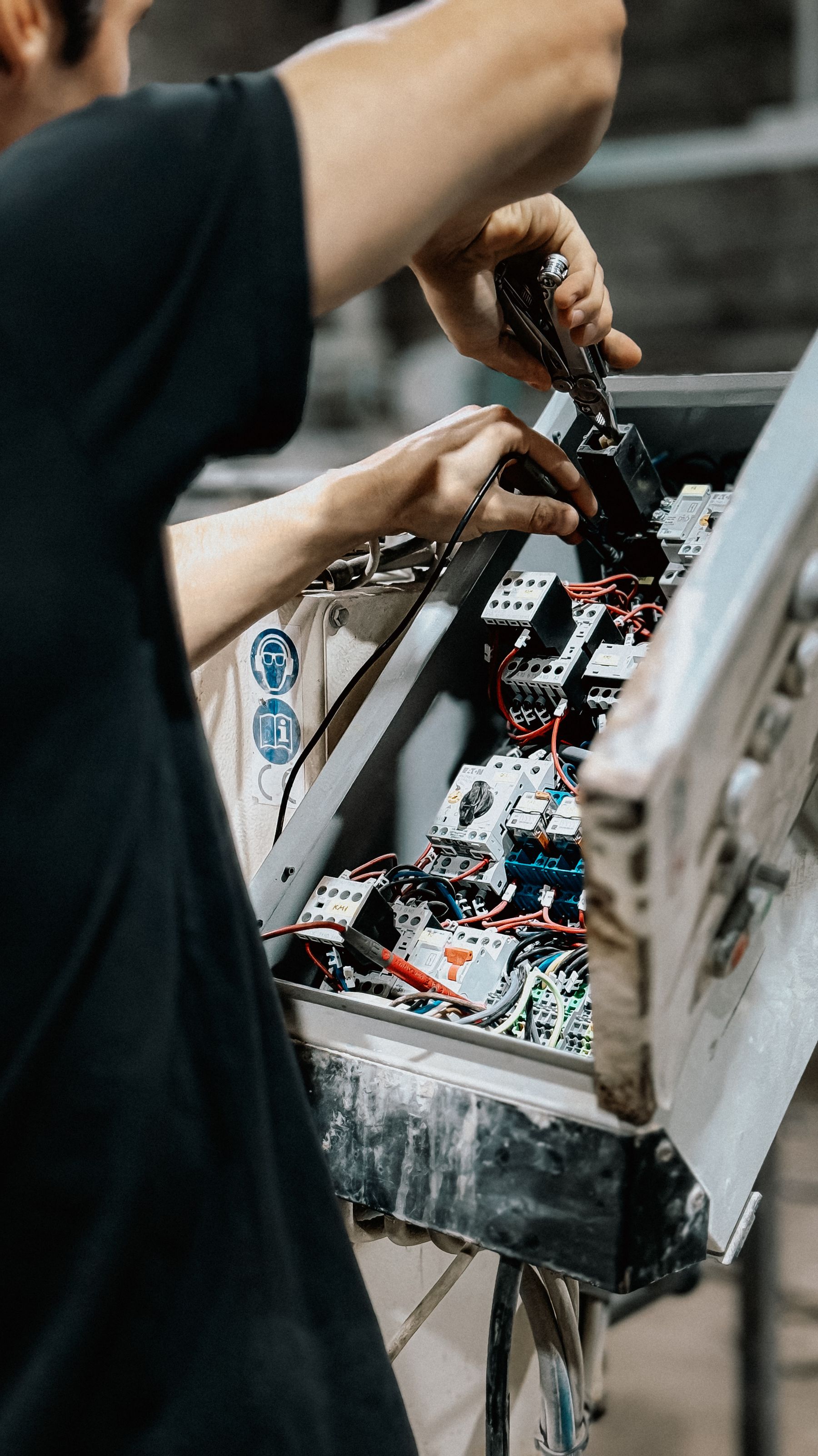
Industrial connector selection guide
M8 vs M12 Sensor Connectors: Choose the Interface, Not Just the Diameter
M8 saves installation space. M12 offers a wider range of established signal, network, and power interfaces. Neither size guarantees a pinout, current rating, data speed, or IP rating. Use this guide to select the complete connection that your sensor and machine actually require.
- M8 and M12 standards mapped
- Signal, IO-Link, Ethernet, and power
- Ingress, torque, cable, and validation checks
Choose M8 when the device and cable route are genuinely space-constrained and an exact M8 configuration meets every electrical and environmental requirement. Choose M12 when the installed system, I/O block, network, or power interface calls for an M12 coding. Then verify coding, contacts, pin assignment, gender, current and voltage, cable, shielding, locking, temperature, and the IP rating of the mated assembly.
Start with the correct definition
M8 and M12 describe connector thread families, not complete specifications
The number identifies the nominal metric coupling-thread family. It is only the first line of a connector description. Two connectors can both be M12 and still be impossible, unsafe, or inappropriate to mate.
Smaller interface
- Useful on compact sensors and crowded machine areas
- Available with multiple contact counts and codings
- Requires exact product ratings and mating details
Broader interface ecosystem
- Common across sensors, I/O, networks, and power
- Many codings intentionally prevent mismating
- Diameter alone does not identify function or rating
Do not confuse sensor housing size with connector size. “M8 sensor” or “M12 sensor” may describe the threaded barrel of a cylindrical sensor. That sensor could have a fixed cable, a pigtail, or a connector of another family. Record the sensor body and the electrical connector as separate items.
M8 vs M12 at a glance
Use size as a packaging decision, then qualify the exact interface
IEC standards define multiple configurations inside both families. The table shows practical selection tendencies, not blanket ratings for every connector.
| Decision point | M8 connector | M12 connector | What the buyer must verify |
|---|---|---|---|
| Packaging | Smaller coupling and usually a smaller cable-end envelope | Larger coupling with more room for varied interfaces | Receptacle clearance, tool access, bend radius, and right-angle orientation |
| Standard scope | IEC 61076-2-104 covers M8 screw and nominal 8 mm snap locking; specialized M8 data/power interfaces are covered elsewhere.1,3 | IEC 61076-2-101 covers M12 screw-locking configurations; other parts cover X-coded and push-pull variants.2,4,5 | Exact detail standard, edition, coding, and manufacturer drawing |
| Contacts and pinout | Multiple contact counts exist; do not reduce M8 to “3 or 4 pin” | Multiple contact counts exist; identical shells can carry different keying | Numbered contacts, function of every pin, male/female side, and viewing direction |
| Signal and power | Suitable products exist for standard sensor signals and selected data/power uses | Broad portfolio for sensor signals, industrial networks, and coded power interfaces | Voltage, current per contact, total connector load, temperature derating, conductor size |
| Data | Selected M8 codings support industrial data; performance depends on the full channel | D- and X-coded M12 are common Ethernet examples, with different performance classes | Protocol, category, frequency or bit rate, shielding, cable length, and switch/device port |
| Ingress | Both families can be offered in high-ingress product designs. Coding does not automatically create an IP rating. | Rating when mated, compatible counterpart, seal condition, assembly method, and unmated protection | |
| Best reason to choose | Required interface fits a compact machine envelope | Required interface matches the machine ecosystem or function | Selection must remain compatible through service, spares, and replacement |
Standards map
There is no single “M8 and M12 standard” that covers every variant
A compliant drawing should identify the relevant detail standard or interface specification. These four references explain why a family name alone is incomplete.
M8 screw or snap locking
The 2026 edition covers 3-way through 12-way connectors for data or frequencies below 100 MHz, and for signal/power in its stated scope.1
M12 screw locking
The 2024 edition covers 2-way through 17-way M12 connectors and uses coding to prevent non-intermateable interfaces from being joined.2
Dedicated data interfaces
Separate parts cover M8 D/P-coded interfaces and M12 X/H-coded interfaces. Data capability belongs to the coded system, not the diameter alone.3,4
M12 inner push-pull
Standardized push-pull M12 interfaces exist for signal, data, and power. Push-pull should be evaluated by its specified retention and environment, not dismissed as inherently weak.5
Mechanical fit
Check the installation envelope, not only the thread diameter
A compact connector can still fail to fit when the cable boot, bend radius, coupling tool, or neighboring port is ignored. A right-angle plug can reduce depth but introduce an orientation problem. A field-wireable connector can be larger than a molded cordset of the same family.
- Measure the entire mated length. Include receptacle, coupling, boot, cable bend, and strain-relief zone.
- Leave assembly access. The technician must be able to mate, torque, inspect, and replace the connector without dismantling unrelated parts.
- Model port density. Check adjacent connectors, labels, valve manifolds, guards, and panel-door clearance.
- Protect the cable route. Respect the cordset bend radius and use a dynamic-rated cable where repeated flexing occurs.
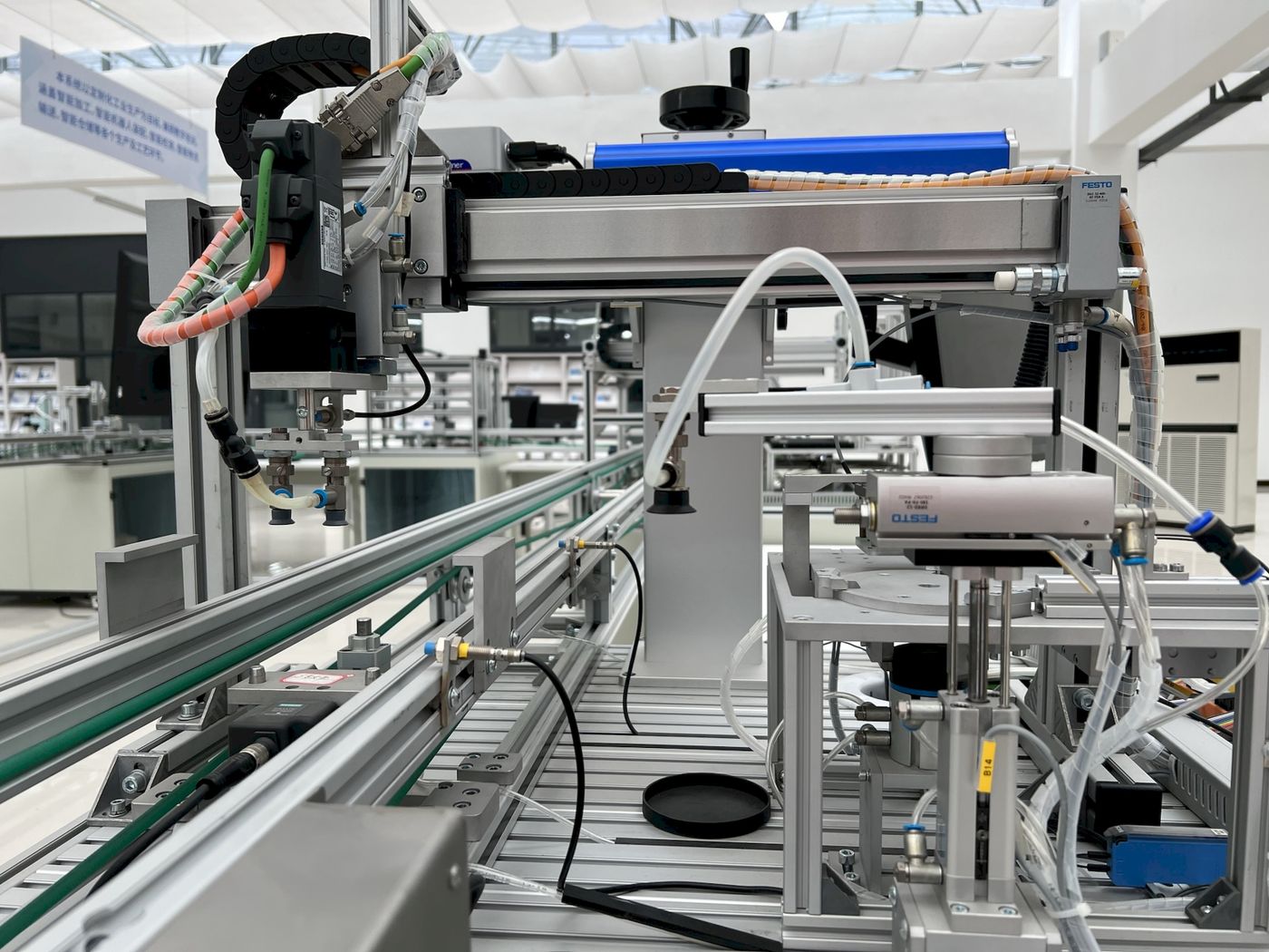
Coding and pin assignment
Coding is the functional key; pinout is the wiring contract
The coding controls which interfaces are intended to mate. It does not tell you every pin function, electrical limit, or cable property. Always pair the coding with the device pinout and connector drawing.
General sensor and actuator use
Common for discrete I/O, analog signals, and IO-Link device connections. Contact count and pin assignment still vary.
Selected fieldbus interfaces
Appears in established automation networks. Match the actual bus specification and installed equipment.
Industrial Ethernet example
Often used for two-pair, 100 Mbit/s Ethernet channels. Confirm category and channel requirements.
Higher-performance Ethernet example
An eight-contact M12 interface used in channels reaching multi-gigabit performance when the complete system is rated accordingly.
Power codings are a separate decision. M12 S-, T-, K-, L-, and other coded interfaces appear in different AC/DC power applications. Do not substitute a familiar A-coded sensor connector for a power-coded interface. This list is illustrative, not a complete catalog of every coding.
Voltage, current, and temperature
There is no universal M8-versus-M12 current table
Ratings change with coding, number of loaded contacts, contact design, conductor size, cable construction, ambient temperature, installation, and the selected mating pair. The standard scope is not a substitute for the product datasheet.
Read the exact connector rating
Record rated voltage, current per contact, total current restrictions, pollution or overvoltage conditions where stated, and conductor size.
Apply the published derating curve
Current capability decreases as temperature rises. IEC 60512-5-2 provides a test method for deriving current-temperature derating curves; it does not create one universal curve for every connector.7
Check the weakest component
The safe circuit limit is constrained by the device port, receptacle, plug, cable conductors, junction or I/O module, and protective device—not the connector shell alone.
One manufacturer family changes rating with contact count
A TE panel-connector family lists different voltage and current values across its M8 and M12 contact arrangements. That is the useful lesson: even products from one manufacturer do not support a single “M8 rating” or “M12 rating.”10
Procurement rule: put the minimum continuous current, peak/inrush current, maximum ambient temperature, number of simultaneously loaded contacts, cable length, and voltage-drop limit on the inquiry. Ask the supplier to identify the exact part-number rating and derating basis.

Data and IO-Link
Protocol first, connector second
A round connector does not convert a cable into an Ethernet or IO-Link channel. Select the communication system, then use the coding, cable category, shielding, and pin assignment required by that system.
- IO-Link can use M12, M8, or M5. The technology uses a standardized three-wire sensor/actuator connection; the physical size is determined by the device and master implementation.8
- IO-Link cable length is limited. The IO-Link system description specifies a maximum of 20 m between master port and device using the described standard cable arrangement.9
- Port Class A and B differ. Confirm how pins 2 and 5 are used before mixing devices, masters, hubs, and cable assemblies.
- Ethernet performance is channel-specific. A D- or X-coded connector must be paired with the correct cable and equipment ports. An adapter cannot upgrade the data category.
Ingress, vibration, and EMC
An IP code belongs to a tested assembly and condition—not to “M12” or “X-coded”
IEC 60529 defines the IP classification system for enclosure protection.6 For a sensor connection, the published rating normally depends on compatible parts being fully mated and assembled as instructed.
Ingress state
Confirm whether the rating applies only when mated. Protect open ports with the specified sealing cap during shipping, cleaning, and service.
Locking method
Threaded and standardized push-pull systems can both be robust when used within their specification. Check retention, vibration, and mating-cycle data.
Assembly torque
Use the value and tool specified for the exact plug and receptacle. A generic M8 or M12 torque can under-compress a seal or damage the interface.
Shield and grounding
For analog signals and noisy environments, select the required shielded assembly and follow the machine grounding and EMC design.
Also qualify oil, coolant, cleaning chemicals, UV exposure, ozone, weld spatter, temperature, drag-chain use, torsion, and jacket material. “IP67” alone says nothing about chemical compatibility or repeated cable movement.
Application selector
Select the connection task—not the connector you already expect to buy
Choose the closest application. The result is a starting interface family and a verification list, not a substitute for the device and cable datasheets.
Start with M8 only when the space saving is real
A compact M8 A-coded assembly can be appropriate when the exact sensor and I/O pinout match and the cable route leaves enough service space.
- Confirm sensor output, supply voltage, and pin assignment.
- Check cable-end diameter, boot length, bend radius, and assembly access.
- Move to M12 if the installed I/O ecosystem or environmental requirement makes it the more maintainable choice.
Common machine scenarios
What changes the answer in real applications
The final choice is usually controlled by the installed system and maintenance plan, not by a universal “better connector.”
| Application | Likely starting point | Decision-changing details | Failure to avoid |
|---|---|---|---|
| Compact gripper or end effector | M8 when the device offers the required interface | Moving cable, torsion, robot dress pack, right-angle orientation | Choosing a small plug with a cable that is not rated for motion |
| Conveyor sensor network | M12 A-coded is common for sensor/I/O connections | Port standardization, cable lengths, spare parts, NPN/PNP, NO/NC | Matching the shell while missing the output or pinout |
| IO-Link device | Match the master port and device; M8 and M12 can both be valid | Port Class A/B, device current, cable length, hub topology | Assuming IO-Link always means one fixed M12 pinout |
| Industrial Ethernet | Choose the protocol and rated coded channel | 100 Mbit/s vs 1/10 Gbit/s, category, shielding, switch ports | Using an adapter or cordset that reduces channel performance |
| High-current load | Dedicated power interface and circuit design | Continuous/peak current, loaded contacts, derating, voltage drop | Using shell size as a current rating |
| Washdown machine | Either family if the complete mated assembly is qualified | Ingress state, chemicals, jacket, seals, torque, open-port caps | Assuming M12 or X coding automatically means IP69/IP69K |
Retrofit and adapters
An M8-to-M12 adapter solves only the problems it is designed to solve
Factory-made M8-to-M12 cordsets and adapters are widely available, but the change in shell size does not prove electrical or protocol compatibility. Treat the adapter as another component in the channel.
- Verify the contact-to-contact map rather than relying on wire colors.
- Check whether shield continuity and connector-body bonding are required.
- Confirm current, voltage, data category, cable length, and environmental ratings after adaptation.
- Document the final assembly as a serviceable part number, not an informal combination.
- For safety-related circuits, follow the safety-system manufacturer’s validated architecture and component requirements.

RFQ and purchasing checklist
Put these ten fields on the connector inquiry
A complete request prevents a “mechanically fits, electrically wrong” delivery and makes second-source review much faster.
Family and locking
M8 or M12, screw, snap, or standardized push-pull interface.
Coding and contacts
Exact coding, number of contacts, male/female side, and key orientation.
Pin assignment
Signal name for every pin and the viewing direction used in the drawing.
Electrical load
Supply voltage, continuous/peak current, loaded contacts, and allowable voltage drop.
Protocol or signal
Discrete, analog, IO-Link, fieldbus, Industrial Ethernet, or power function.
Cable construction
Length, conductor size, shield, jacket, fixed or dynamic use, bend and torsion needs.
Environment
Temperature, ingress, oil, coolant, chemical, UV, weld-spatter, and washdown exposure.
Mechanical envelope
Straight/right-angle, mated length, port spacing, tool access, and strain relief.
Compliance evidence
Applicable standard, approvals, test ratings, and installation instructions.
Service plan
Mating cycles, spare cordsets, caps, torque tools, labeling, and approved alternates.
Commissioning sequence
Validate the connection before the machine enters production
A short bench and machine test catches pinout, assembly, cable-route, and load problems before they become intermittent downtime.
Inspect
Confirm coding, contacts, seals, thread condition, cable label, and orientation against the drawing.
Map
Continuity-test the pin assignment and check for shorts before applying power to an unfamiliar assembly.
Assemble
Mate fully, use the specified torque or locking procedure, and establish strain relief without twisting the cordset.
Load test
Measure supply voltage at the device under operating load and monitor signal or network diagnostics.
Stress check
Run motion, vibration, thermal, and cleaning conditions relevant to the machine, then inspect and record the result.
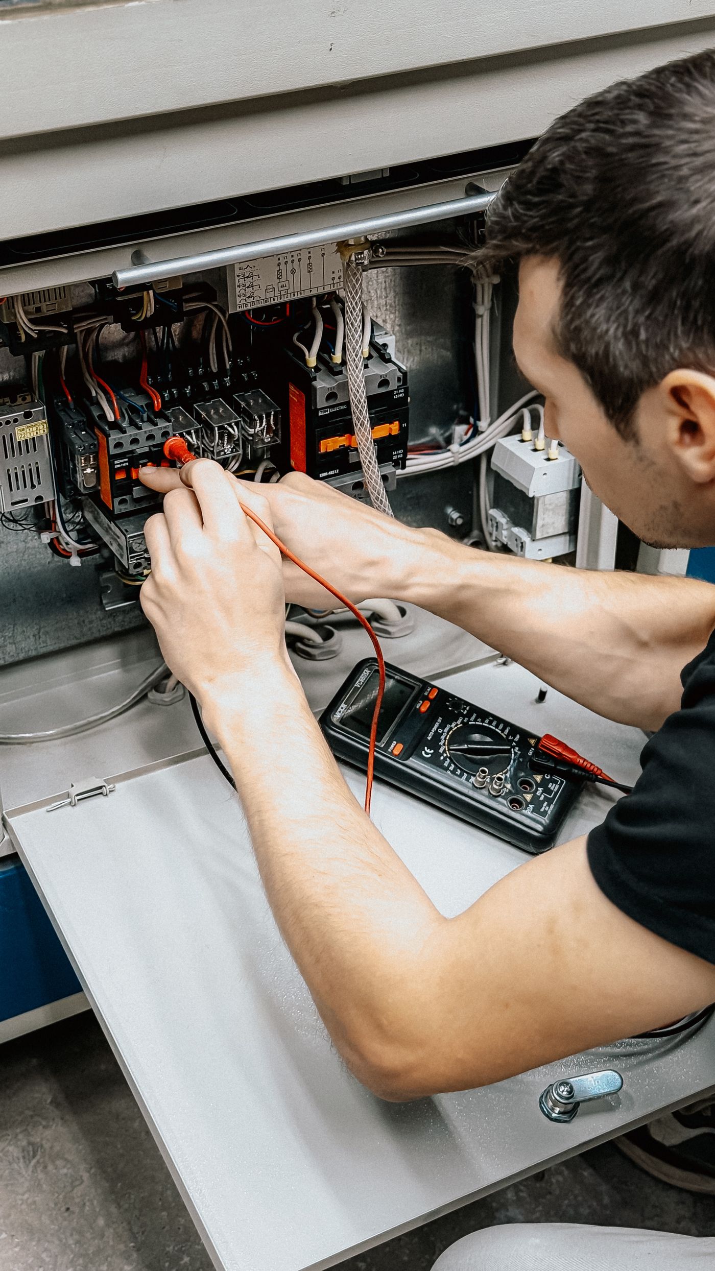
Verification evidence
Record what was tested, not only “connection OK”
A useful commissioning record identifies the sensor, cordset, receptacle or I/O port, pinout revision, assembly method, supply measurement, diagnostics, and test conditions.
- Photograph connector labels and cable routing before guards close.
- Record no-load and loaded voltage at the device when voltage drop matters.
- Save IO-Link event or process-data checks, or network diagnostics for data channels.
- Include the torque tool or assembly method where sealing depends on proper mating.
- Mark approved replacement cordsets and caps in the spare-parts list.
Troubleshooting
When a sensor connection is intermittent, inspect the interface systematically
Replacing the sensor first can hide the actual cable, pinout, voltage-drop, sealing, or routing fault.
Device has no power
Check pin assignment, polarity, loaded voltage at the device, conductor continuity, and supply protection.
Output is always on or off
Verify NPN/PNP, NO/NC, input common, output pin, and whether an adapter changes the contact map.
Fault appears during movement
Inspect bend radius, torsion, strain relief, drag-chain rating, connector retention, and cable breaks near the boot.
Network drops intermittently
Check the full channel category, shield termination, routing near drives, connector seating, and diagnostics.
Water or coolant ingress
Inspect mating completeness, seal damage, thread contamination, correct parts, open ports, and chemical compatibility.
Connector runs warm
Stop and review contact condition, current, loaded contacts, ambient temperature, derating, conductor size, and mating quality.
For a broader fault-isolation sequence, use the XSZ Sensor Troubleshooting Guide.
Reduce connector mismatch before ordering
Send XSZ the device pinout and machine conditions—not only “M8” or “M12”
Include connector photos or drawings, sensor model, I/O or master port, supply, signal or protocol, cable length, environment, motion, and required approvals. We can help review the sensing connection as part of the sensor selection.
Continue the selection
Match the connector to the sensor and control system
Frequently asked questions
M8 vs M12 sensor connector FAQ
Is M12 always better than M8?
No. M12 has a broad ecosystem and may be easier to standardize on many machines, while M8 can provide valuable space savings. The better choice is the exact interface that meets the device, electrical, communication, environmental, mechanical, and service requirements.
Does an M12 connector carry more current than an M8 connector?
Not as a universal rule. Exact ratings depend on coding, contact arrangement, product design, cable conductor size, loaded contacts, ambient temperature, and derating. Compare exact part numbers and the complete circuit.
Can M8 be used for IO-Link?
Yes. IO-Link can be implemented with M12, M8, or M5 connectors. Match the device, master port, pin assignment, port class, cable, current, and the IO-Link cable-length requirement.
Is every 4-pin M12 connector wired the same way?
No. Coding, pin numbering, gender, viewing direction, and device function matter. Never approve a replacement from “M12, 4-pin” alone; compare the pinout drawings.
Does X-coded M12 automatically mean IP68 or IP69K?
No. X coding identifies a data interface. Ingress protection is a separate tested product or assembly rating and usually depends on compatible parts being properly mated. Check the manufacturer’s conditions.
Can I connect an M8 sensor to an M12 I/O block?
Often, a purpose-built adapter or cordset can make the mechanical transition. It is acceptable only when the pin map, signal, voltage, current, shielding, cable, protocol, and environmental ratings remain compatible.
What torque should I use for M8 and M12 connectors?
Use the assembly torque published for the exact connector and mating component. Do not apply one generic torque to every M8 or M12 product, because coupling and sealing designs differ.
Which information is most important on an M8 or M12 connector RFQ?
Specify family and locking method, coding, contact count, gender, pinout, signal or protocol, voltage and current, cable length and construction, shielding, environment, motion, mechanical orientation, and applicable approvals.
Technical references
- IEC 61076-2-104:2026, M8 screw-locking or nominal 8 mm snap-locking circular connectors.
- IEC 61076-2-101:2024, M12 screw-locking circular connectors.
- IEC 61076-2-114:2020, M8 D- and P-coded data and power connectors.
- IEC 61076-2-109:2014, M12 X- and H-coded connectors for data transmission.
- IEC 61076-2-012:2020, M12 inner push-pull connectors.
- IEC 60529, degrees of protection provided by enclosures (IP Code).
- IEC 60512-5-2:2002, current-temperature derating test.
- IO-Link Community: Technology, standardized point-to-point sensor and actuator communication.
- IO-Link System Description, cabling, port classes, and 20 m master-to-device connection limit.
- TE Connectivity M8/M12 Panel Mount Connector overview, example family ratings that vary by size and contact arrangement.
Image credits
- Bulat843 / Pexels, electrical control-panel technician.
- KJ Brix / Pexels, modern automation machinery.
- Anton Mislawsky / Pexels, industrial machine electronics.
- Erik Mclean / Pexels, industrial electrical equipment.
- Bulat843 / Pexels, multimeter verification.