Mechanical installation guide
Sensor Mounting Brackets: Build a Stable Detection Reference
A sensor mounting bracket controls position, angle, sensing gap, cable load, and resistance to vibration. If that reference moves, the output can move even when the target does not. Choose the bracket from the sensor's installation instructions, the required detection geometry, real machine loads, environment, adjustment needs, and service procedure.
- Geometry before material
- Model-specific torque and clearance
- Validate under real vibration and temperature
Direct answer
What makes a good sensor mounting bracket?
A good bracket keeps the sensor inside its approved mounting geometry throughout operation, cleaning, maintenance, and replacement. It is stiff enough for the real load, compatible with the environment, secured with the specified hardware and torque, clear of the sensing field, and adjustable only where adjustment is genuinely needed.
The bracket is part of the measurement chain
The sensor measures from its own moving reference.
A proximity switch reports whether a target crosses its sensing zone. A photoelectric sensor evaluates a light path. A safety light curtain depends on sender-receiver alignment. A distance sensor reports from its front face. None of these devices can independently know whether the machine target moved or the sensor bracket moved.
The bracket therefore establishes three practical quantities: position, where the sensor is located; orientation, where its sensing axis points; and standoff, the working distance or gap. It also transfers cable forces, shock, vibration, thermal movement, and service loads into the sensor.

Five links determine stability
Follow the load path from machine frame to sensing face.
A thick bracket cannot compensate for a flexible machine panel, loose rail clamp, poor joint, or cable that continually pulls on the sensor.
Machine datum
The frame, extrusion, plate, guard, or fixture to which the bracket attaches. Verify that this base is stable relative to the target.
Base joint
Fasteners, rail clamp, weld, adhesive joint, or adapter that transfers load into the machine structure.
Bracket body
Its length, section shape, gussets, slots, bends, and material control static deflection and dynamic behavior.
Sensor interface
Nuts, clamp, screws, dovetail, end-cap bracket, groove, process adapter, or manufacturer accessory.
Cable and target
Cable movement, connector access, target impact, cleaning tools, product jams, and guarding can load the final assembly.
Geometric planning tool
Estimate how angular error moves the sensing axis.
A small angle can create a meaningful lateral shift at long standoff. Enter the planned distance and angular deviation to visualize the geometry before assigning a tolerance.
Bracket angle estimator
Use positive values within the practical range of your mounting concept.
Calculated geometry
At 500 mm, a 1° angle shifts the axis about 8.73 mm sideways. Whether that is acceptable depends on beam/cone size, target dimensions, alignment margin, sensing mode, and the exact sensor specification.
Choose by sensing geometry
Different sensor families place different demands on the bracket.
The useful bracket is the one that preserves the sensing field, mounting clearances, alignment method, output stability, and service access defined for the actual device.
Cylindrical proximity sensors
Use the approved nuts, clamp, or sleeve without loading the sensing face. For inductive models, flush and non-flush mounting require different surrounding-metal clearance. Preserve the set sensing gap through vibration and maintenance.
Confirm: thread size, nut position, torque, metal clearance, target gapPhotoelectric sensors
Keep the beam clear and the sensor aligned with its target, reflector, or receiver. Slotted adjustment helps commissioning, but the final joint must resist movement. Target motion across the beam often creates a clearer switching edge.
Confirm: optical mode, beam path, angle, background, adjustment lockSafety light curtains
Sender and receiver brackets must support alignment while maintaining the protective-field geometry and safety distance established by the machine risk assessment. Use only compatible accessories and the device instructions.
Confirm: approved bracket, support position, torque, alignment, safety validationFiber optic sensing heads
Protect the small head and preserve its working distance while routing the fiber within its permitted bend and motion limits. Do not let cable tension rotate the head or turn a sharp bracket edge into a stress point.
Confirm: head geometry, spot/beam, cable route, bend limit, clamp methodMagnetic cylinder switches
The mounting interface must match the cylinder groove, tie rod, or accessory band and place the switch in the correct piston detection zone. Prevent slide after adjustment and protect the lead from cylinder movement.
Confirm: cylinder profile, groove or band, switch orientation, cable travelDistance and level sensors
Longer standoff magnifies angular shift. Mounting must also respect blind zones, nozzles, beam or cone geometry, tank walls, target angle, process adapters, and any specified perpendicularity.
Confirm: working zone, axis, target surface, process geometry, thermal movementMaterial selection
Choose the material after defining stiffness, environment, mass, and joint design.
There is no universally best bracket material. A compact bent stainless bracket can outperform a long aluminum arm because geometry controls stiffness as strongly as material. A polymer bracket may be correct for isolation or corrosion but unacceptable where creep, temperature, impact, or dimensional stability dominate.
Compare the actual alloy or polymer grade, thickness, section shape, heat treatment, coating, chemical compatibility, service temperature, creep, UV exposure, galvanic pairing, cleaning method, and manufacturing tolerance. “Aluminum,” “stainless,” and “plastic” are categories, not finished specifications.
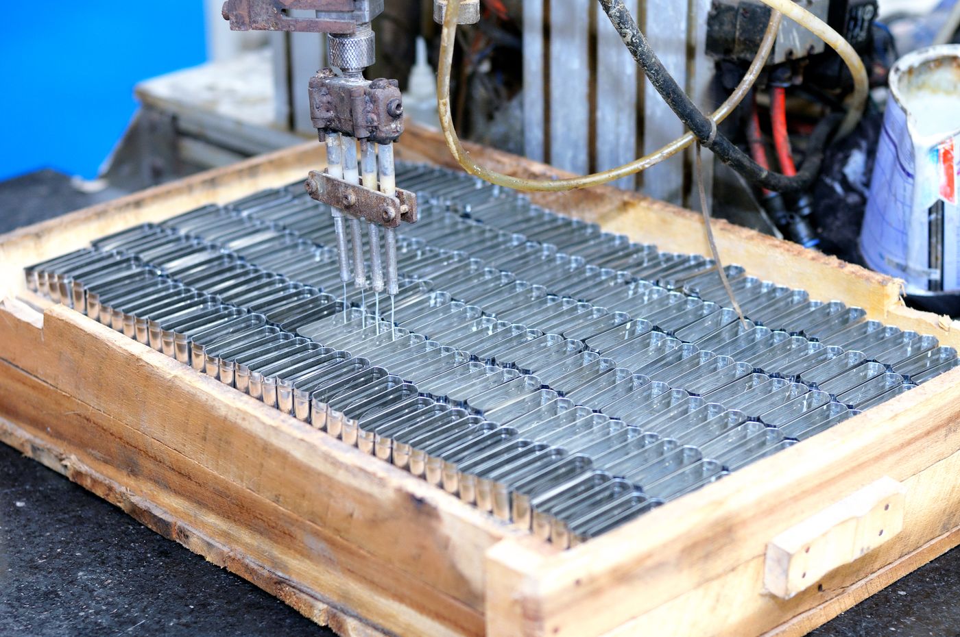
| Material route | Useful reasons to shortlist it | Main risks to check | Evidence required before approval |
|---|---|---|---|
| Coated carbon steel | High stiffness at practical thickness, economical stamped or bent construction, familiar fabrication. | Coating damage, corrosion at cut edges or trapped moisture, added mass, chemical incompatibility. | Steel grade, thickness, coating system, salt/moisture exposure, edge treatment, cleaning chemicals, fastener pairing. |
| Stainless steel | Corrosion resistance and cleanability for many humid, washdown, outdoor, or chemical environments. | Grade selection, chloride or chemical exposure, galling, fabrication distortion, higher mass and cost. | Exact stainless grade, finish, weld treatment, chemical concentration, temperature, cleaning cycle, compatible fasteners. |
| Aluminum alloy | Low mass, easy machining, useful for adjustable fixtures or moving equipment when correctly sized. | Lower elastic modulus than steel, thermal expansion, thread wear, galvanic pairing, coating or chemical attack. | Alloy and temper, anodizing/coating, section geometry, inserts, load, temperature range, adjacent metals. |
| Engineering polymer or composite | Electrical or thermal isolation, low mass, corrosion resistance, complex molded geometry. | Creep, moisture absorption, temperature, UV, chemical exposure, fastener crushing, lower joint stiffness. | Grade-specific mechanical data over time and temperature, inserts, torque limit, chemical compatibility, production process. |
| Additively manufactured part | Fast fit validation, low-volume geometry, cable-routing prototypes, or production when process and material are qualified. | Print orientation, anisotropy, voids, creep, surface accuracy, heat, chemical resistance, inconsistent process control. | Material and process specification, orientation, inspection, environmental conditioning, load test, repeatability, production control. |
Bracket architecture
Select the adjustment method without creating a permanent weak joint.
Adjustment is valuable during commissioning, but every slot, swivel, rod, or extra adapter adds interfaces that can move. Preserve only the degrees of freedom needed for alignment.
Vibration, shock, and resonance
Stiffen, isolate, or relocate only after measuring the disturbance.
A bracket has static deflection and dynamic behavior. A mount that looks rigid by hand can amplify motion near one of its natural frequencies, while a soft isolator can amplify low-frequency movement or distort what an inertial sensor is supposed to measure.
Reduce movement at the source
- Move the sensor closer to the support and shorten unsupported length.
- Increase section depth, add a return flange or gusset, and avoid thin flat strips where bending dominates.
- Attach to the structure that moves with the target, not a flexible guard or access panel.
- Remove loose joints, worn clamps, unseated washers, damaged threads, and cable forces.
- Relocate away from direct impact, product jams, vibrating covers, and high-energy machine components.
Validate the dynamic response
- Record machine speed, motor and pump frequencies, reciprocating events, impacts, and operating modes.
- Measure bracket motion or sensor output during run-up, steady state, coast-down, startup, and cleaning.
- Use modal or frequency-response testing when detection tolerance and downtime justify it.
- Apply isolation only with a defined supported mass, disturbance spectrum, required bandwidth, and environmental compatibility.
- Use IEC 60068 vibration or shock procedures only when the product or project specification calls for an applicable test severity and mounting method.

Fasteners and locking
Use the specified torque, not a universal bolt-size chart.
Installation torque produces joint preload through a friction-sensitive process. The correct value depends on fastener property class and material, thread condition, lubrication or coating, nut or tapped-hole strength, washer, joint material, reuse policy, locking feature, and the sensor manufacturer's limit.
For a threaded sensor body or plastic bracket, excessive torque can damage the housing or mount. Too little clamp force can allow slip or loss of alignment. Manufacturer instructions for the exact sensor and bracket take priority over a generic M3, M4, M5, or M6 recommendation.
The bracket must not disturb the field
Mechanical fit and sensing fit are two separate checks.
A bracket may hold the housing securely yet still reduce range, create false triggers, block a beam, reflect an echo, or expose a protective field to misalignment.
Optical alignment without guesswork
Set the beam path first, then lock the bracket.
Photoelectric installation guidance commonly emphasizes precise alignment and target movement across the sensing field. The exact procedure depends on whether the target reflects light, interrupts a reflector return, or breaks a beam between separate devices.
Alignment sequence
- Mount the sensor inside its specified working range with enough adjustment for tolerance, not unlimited movement.
- Align to the actual target, reflector, or receiver while monitoring signal, excess gain, alignment aid, or diagnostic value.
- Run the smallest, darkest, clearest, glossiest, and most angled target through the full allowed path.
- Tighten in a sequence that does not rotate the sensor or pull the slot to one end.
- Recheck signal after final torque, cable clamping, guarding, and nearby equipment are complete.
Replacement strategy
- Add a hard stop, locating edge, pin, key, engraved scale, or documented dimension when rapid replacement matters.
- Make tool access possible without removing unrelated guards or stressing the connector.
- Store the approved teach settings and output logic with the machine record.
- Require a detection challenge after replacement; mechanical repeatability does not eliminate functional verification.
- Protect the lens from impact while keeping the optical path and cleaning access open.
Safety light curtain brackets
A safety-related mount must preserve the validated protective function.
Safety light curtain mounting is not ordinary presence-sensor installation. Sender and receiver position, protective-field height, resolution, reach, mirrors, muting components, safety distance, blind areas, restart behavior, and machine stopping performance belong to the safety design.
Bracket requirements
- Use brackets and accessories approved or specified for the exact light curtain family.
- Position supports as instructed for the housing length and expected vibration.
- Use the specified tightening torque; too much can damage a bracket while too little can permit slip.
- Keep alignment adjustment available without allowing the assembly to rotate after final tightening.
- Protect the device from collision without creating a bypass or unprotected access path.
Validation after mounting
- Complete the manufacturer alignment and diagnostic procedure for sender and receiver.
- Perform the required test-rod or protective-field test along the full protected area.
- Verify safety distance and stopping performance through the machine risk assessment and applicable safety standards.
- Test restart, reset, EDM, muting, blanking, and fault behavior where those functions are used.
- Repeat inspection after impact, bracket adjustment, device replacement, or machine modification.
Cable force and service clearance
A stable bracket can still move when the cable becomes a spring.
A short, tightly bent, moving, or unsupported cable can apply force and torque to a small sensor. Connector changes, drag-chain motion, door movement, temperature, and washdown hoses can turn that load into gradual drift or an intermittent electrical fault.
Strain relief
Support the cable on a stable structure so normal cable movement does not pull the sensor or connector. Follow the cable and connector manufacturer's bend, clamp, and motion instructions.
Verify movement with every axis, door, and guard in motionService loop
Provide enough slack for connector access and replacement without a tight bend or snag. Too much unsupported loop can enter the sensing field, product path, or moving machinery.
Design the loop from actual connector and tool clearanceRouting separation
Keep sensor cables away from sharp edges, hot surfaces, weld spatter, high-energy conductors, pinch points, and uncontrolled abrasion. Apply shielding and grounding rules for the signal system.
Inspect the complete route, not only the final 100 mmConnector orientation
Rotate or position the bracket so the mating connector, cable exit, status indicator, teach button, and label remain accessible without dismantling alignment.
Check wrench and hand clearance before releasing drawingsFiber optic cable
A fiber can transmit the optical signal while mechanically damaged or heavily attenuated. Protect non-bendable head sections and meet static or repeated-flex specifications for the exact fiber.
Use guides and clamps that do not crush or sharply bend the fiberIdentification
Label the sensor, connector, cable, channel, approved position, and output logic so maintenance does not reconnect the wrong device or disturb an adjacent bracket.
Make replacement steps visible in the machine documentationInstallation workflow
Install and approve a sensor bracket in six controlled steps.
The sequence separates geometry, mechanics, sensing performance, and electrical integration so a passing output is supported by evidence.
Define the detection requirement
Record target, operating distance, allowed position and angle, speed, sensing mode, output, response, environment, maintenance access, and failure consequence.
Read the model instructions
Extract approved mounting method, hardware, torque, flush/non-flush clearance, working zone, beam or cone, orientation, environmental limits, and cable rules.
Design the load path
Select a stable machine datum, minimize unsupported length, size the section, control adjustment, protect against impact, and preserve the sensing field.
Assemble with a controlled joint
Use specified fasteners, washers, inserts, locking method, surface condition, torque tool, and sequence. Add strain relief without loading the sensor.
Align and function-test
Set gap or optical path using real targets. Verify diagnostics and output across minimum, nominal, and maximum positions before and after final tightening.
Challenge and document
Run worst speed, vibration, temperature, contamination, cleaning, adjacent sensors, startup, stop, and product variants. Record position, settings, results, and inspection criteria.
Failure diagnosis
Read the output pattern as evidence of mounting failure.
Mechanical faults often have time, speed, temperature, direction, or maintenance patterns. Reproduce the pattern before re-teaching the sensor.
| Observed symptom | Likely mounting causes | Checks to perform | Corrective direction |
|---|---|---|---|
| Slow drift during warm-up | Bracket or machine thermal growth, cable force change, polymer creep, target fixture movement. | Measure sensor and target position versus temperature; inspect material stack and warm-up timeline. | Shorten path, relate datum to target, change geometry/material, isolate heat where appropriate, compensate only after mechanics are stable. |
| Jitter at one machine speed | Bracket resonance, loose clamp, panel vibration, motor or reciprocating excitation. | Compare output or accelerometer data during speed sweep; inspect joints and support motion. | Relocate, shorten, stiffen, improve joint, alter excitation, or engineer isolation from measured frequency data. |
| Step change after maintenance | Bracket moved in slot, sensor replaced at different depth, nut or reflector position changed, cable re-routed. | Compare witness marks, datum dimensions, photos, torque record, teach values, and connector orientation. | Add repeatable locating features and a documented replacement verification procedure. |
| False trigger after guard closes | Sensor attached to flexible guard, guard enters field, cable bends, reflective panel changes optical background. | Observe bracket and signal while operating the guard; isolate each optical, electromagnetic, or mechanical influence. | Mount to stable frame, reroute cable, clear the field, or change sensing geometry. |
| Range falls after final assembly | Metal predamping, blocked beam, misalignment, reflector or receiver movement, bracket echo, lens obstruction. | Compare signal before/after bracket installation and inspect required clearances from model documentation. | Change bracket geometry, mounting exposure, alignment, or sensing mode and revalidate. |
| Intermittent electrical fault | Connector side load, cable fatigue, pinch point, abrasion, grounding change, water ingress after bracket modification. | Inspect route under motion, measure supply/output under load, flex only within approved diagnostic practice. | Add correct strain relief, route protection, compatible connector orientation, and electrical repair. |
Quotation and design checklist
Send these details before requesting a bracket or sensor recommendation.
A mounting solution cannot be selected from sensor diameter alone. Share the machine geometry and acceptance criteria with the sensor and bracket information.

Application-based sensor support
Match the sensor, bracket, target, and machine as one detection system.
Send XSZ the sensor type, target, working distance, mounting photo or drawing, surrounding metal, vibration, environment, cable and connector, NPN/PNP, NO/NC, and required detection result. This allows the team to review model fit and installation constraints before sample testing.
Frequently asked questions
Sensor mounting bracket FAQ
Why does a sensor mounting bracket affect detection accuracy?
The sensor measures from its own position and orientation. Bracket deflection, slip, vibration, thermal movement, cable force, or poor alignment changes that reference and can change the sensing gap, beam path, measured distance, or target crossing point. The effect depends on the sensing principle, standoff, target, bracket geometry, and required tolerance.
What is the best material for a sensor bracket?
There is no universal best material. Coated steel, stainless steel, aluminum alloy, engineering polymer, composite, or qualified additive manufacturing can each be correct. Choose from stiffness and section geometry, mass, temperature, creep, corrosion, washdown chemicals, galvanic pairing, electrical or thermal isolation, fabrication tolerance, volume, and cost.
How thick should a sensor mounting bracket be?
Thickness cannot be selected without bracket shape, unsupported length, material, load, fastener spacing, adjustment slots, required deflection, vibration spectrum, impact risk, and boundary conditions. A short flanged or gusseted bracket can be much stiffer than a thicker flat strip. Calculate or test the complete load path and verify sensor output under real operation.
How much sensor misalignment is acceptable?
Use the exact sensor instructions and the application's margin. Acceptable angle depends on beam or cone width, target size, sensing mode, reflector or receiver alignment, distance, background, detection zone, and required repeatability. A single one-degree rule is not valid for every proximity, optical, ultrasonic, radar, or safety sensor.
What torque should I use on a sensor bracket?
Use the torque specified for the exact sensor, bracket, and joint. Torque depends on fastener property class and material, thread condition, lubrication or coating, washer, nut or tapped-hole strength, joint material, locking feature, reuse policy, and housing limits. Do not choose torque from bolt diameter alone.
Should I use rubber vibration isolators under a sensor?
Only after defining the disturbance spectrum, supported mass, isolator stiffness and damping, required sensor bandwidth, environmental conditions, and acceptance criterion. Isolation can reduce selected higher-frequency input but amplify motion below or near the isolation system's resonance. Many presence sensors benefit first from a shorter, stiffer mount or relocation to a more stable datum.
Can I use a 3D-printed sensor bracket in production?
Yes, when the material, print process, orientation, inserts, tolerances, creep, fatigue, temperature, UV, chemicals, cleaning, impact, load, inspection, and production consistency are qualified for the application. A printed part should not be treated as prototype-only or production-ready based on the manufacturing method alone.
How should I test a sensor bracket before production release?
Verify dimensions, datum, fasteners, torque, cable route, sensing-field clearance, alignment, and replacement access. Then run all target variants at worst distance, speed, vibration, temperature, contamination, cleaning, startup, stop, and adjacent-sensor conditions. Record mechanical movement, signal margin, missed detections, false triggers, repeatability, fastener condition, and post-test alignment.
Technical references and image credits
Sources used to verify the guide
- ifm Photoelectric Sensor Installation Guidelines — alignment, reflector, receiver, and transverse target movement.
- ifm Inductive Sensor Installation Guidelines — flush and non-flush mounting around metal.
- OMRON E2E Proximity Sensor Documentation — model-specific surrounding-metal distances, mutual interference, nuts, and tightening force.
- SICK C4-RD Safety Light Curtain Instructions — bracket position, vibration considerations, and model-specific torque.
- IEC 60068-2-6:2007 — sinusoidal vibration test procedure and reporting context.
- IEC 60068-2-27:2008 — non-repetitive and repetitive shock test procedure.
- NASA Fastener Design Manual — fastener selection, materials, corrosion, locking, fatigue, joint loading, and torque.
- Hero image: Bulat843 / Pexels.
- Metal fabrication image: Cọ Sơn Thanh Bình / Pexels.
- Fastener adjustment image: cnrdmroglu / Pexels.
- CTA image: Bulat843 / Pexels.
- XSZ proximity sensor product image and category context.
This guide supports planning and supplier discussions. It does not replace the exact sensor and bracket instructions, structural or joint design, machine risk assessment, functional-safety validation, chemical compatibility review, or application testing required for the final installation.