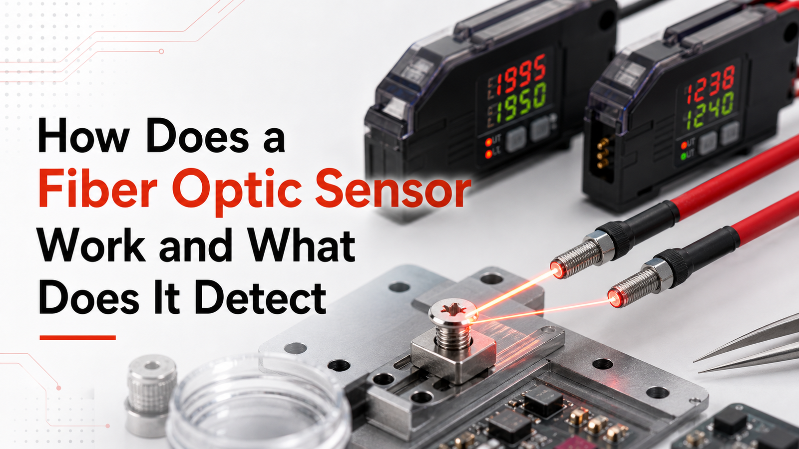
A fiber optic sensor is a light-based detector that sends light through a thin glass or plastic fiber and reads changes in that signal to measure temperature, strain, pressure, vibration, or chemistry. So what is a fiber optic sensor in practice? Intrinsic types use the fiber itself as the sensing element, while extrinsic types relay the signal from a remote sensor. Because they use light instead of electricity, these sensors are immune to electromagnetic interference, and a single fiber can host thousands of sensing points across kilometers of cable.
This guide really works through the questions that matter here. How does it actually work? What can it detect in practice? How is it different from electrical sensors?
What are the main types you will run into? And which specifications should you pay attention to when you are choosing one?
Quick Takeaways
- Fiber sensors measure temperature, strain, pressure, vibration, and chemistry using light signals.
- Choose intrinsic types for direct sensing; extrinsic types relay remote signals.
- Deploy fiber sensors where electromagnetic interference disrupts traditional copper-wire electrical sensors.
- Leverage single fibers hosting thousands of sensing points across kilometers.
- Compare Fiber Bragg Grating and distributed sensing before selecting a technology.
What Is a Fiber Optic Sensor in Simple Terms
A fiber optic sensor is a device that sends light through a thin glass or plastic fiber and reads changes in that light to measure things like temperature, pressure, or strain. Think of the light as a little messenger. It travels down the fiber, gets nudged by whatever is around it, and comes back carrying the answer. As the standard fiber-optic sensor definition puts it, the fiber itself can act as the sensing element, or it can simply relay signals from a remote point back to the electronics.
So what is a fiber optic sensor doing that a copper wire can’t do? The wire carries electricity, while the fiber carries light instead. When something outside the fiber, like heat, bending, or sound, actually touches it, the light’s intensity, wavelength, or phase shifts a tiny bit. A detector spots that shift and turns it into a number you can read.
Why “light as the messenger” beats the electrical model
Light doesn’t care about electrical noise, and that’s really the practical payoff here. A fiber optic sensor stays immune to electromagnetic interference, which is essentially stray electrical signals that scramble ordinary sensors, and it keeps working near high-voltage power lines or inside motors, according to industry sensor engineering sources. The glass core is often thinner than a human hair, around 9 micrometers for single-mode fiber, which is a detail that most spec sheets skip over. That tiny size lets you snake a sensor into a crack, a jet engine, or a beating heart, all places where a bulky electrical probe simply won’t fit.
How Does a Fiber Optic Sensor Actually Work
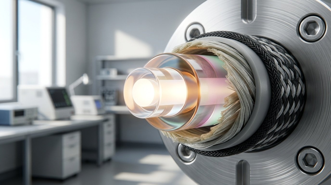
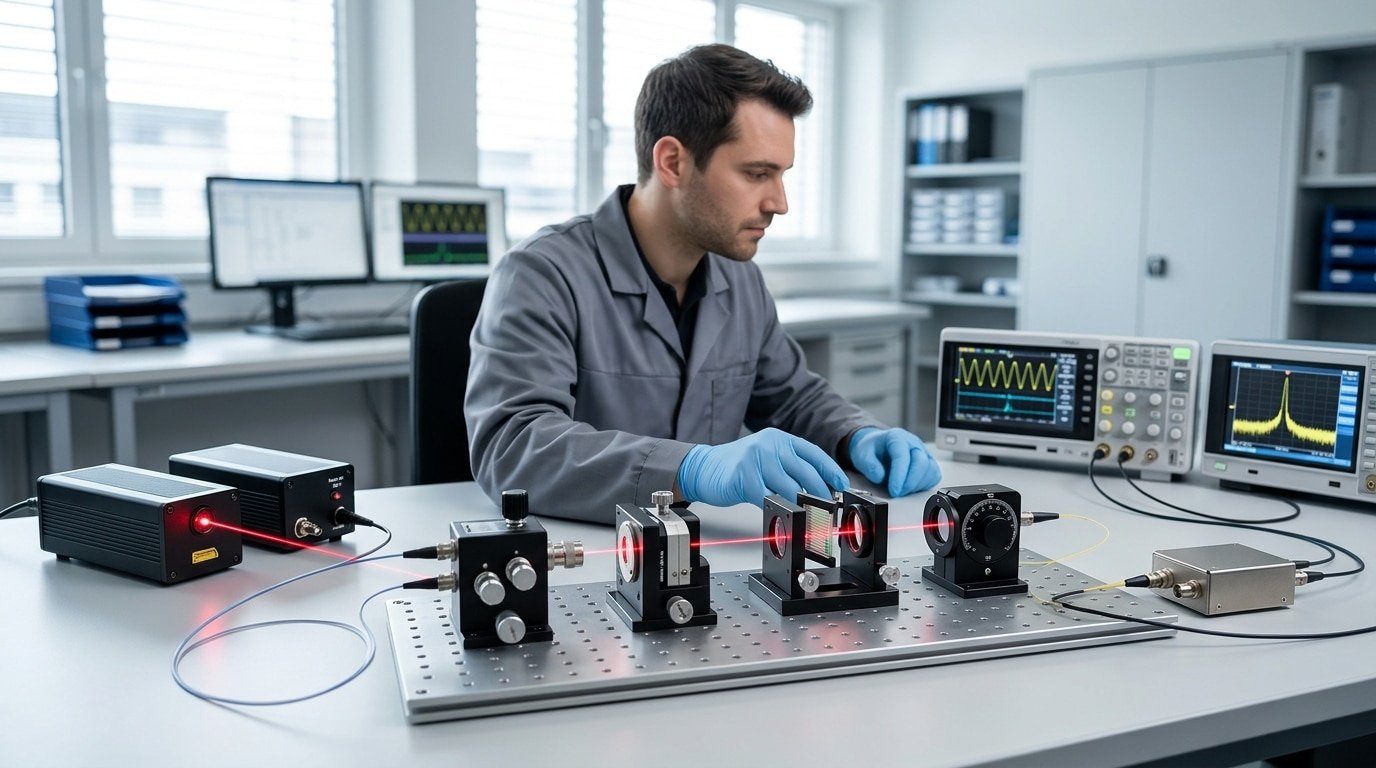
A fiber optic sensor works by sending light down a thin fiber, letting the thing you measure change that light, then reading the change at the far end. A basic system has four parts: a light source (a laser or LED), the fiber that carries and sometimes senses the light, a transducer that reshapes the light with the measured quantity, and a detector with signal-processing electronics, according to optical sensing system design references. That change in light is what tells you the temperature, strain, or pressure.
The measured quantity, heat, force, movement, alters one of four light properties. Understanding what’s a fiber optic sensor really means knowing these four modulation methods.
- Intensity modulation: the amount of returned light rises or falls. Example: a nearby object reflects more light back into the fiber, so the photodiode reads a brighter signal.
- Phase modulation: strain stretches the fiber, delaying the light wave. Example: an interferometer detects a phase shift smaller than one wavelength (under 1.5 µm).
- Wavelength modulation: temperature shifts the reflected color. Example: a fiber Bragg grating reflects a peak wavelength that moves as the fiber heats.
- Polarization modulation: pressure twists the light’s orientation. Example: mechanical stress rotates the polarization angle the detector measures.
Practical tip: wavelength-based sensors resist drift better than intensity ones, because dirt or a loose connector dims intensity but leaves wavelength untouched. That’s why fiber Bragg gratings dominate long-term structural monitoring.
What Can a Fiber Optic Sensor Detect
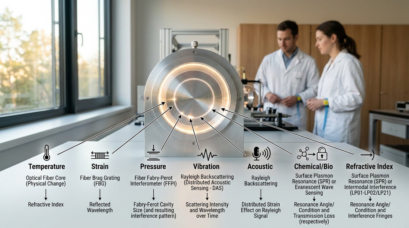
A fiber optic sensor can pick up temperature, strain, pressure, vibration, sound waves moving through the air or a structure, the concentration of a chemical, and the refractive index, which is basically a measure of how much a material bends the light passing through it. Each of these things changes one specific property of the light as it travels down the fiber, whether that is how bright the light is, its wavelength or color, its phase, or its polarization, according to RP Photonics’ optics reference.
That wide range is really the reason one thin strand of fiber can stand in for dozens of separate electrical probes. Below, each thing being measured is matched up with the optical property it affects and a field where it proves useful.
- Temperature: it shifts the Bragg wavelength or changes the Raman backscatter ratio, and power utilities use this to keep an eye on buried cable joints.
- Strain: it stretches the fiber and moves the wavelength, and this is used to watch the structural health of bridges and dams over time.
- Pressure: it bends a thin diaphragm that changes the phase of the light, and this shows up in the downhole tools used in oil and gas work.
- Vibration: it changes the phase of the backscattered light, and this is used to monitor railway track conditions.
- Acoustic waves: they shift the phase of the light along the fiber, and this is used to find leaks in pipelines.
- Chemical concentration: it absorbs certain wavelengths of light, and this is used in gas leak detection and in watching the environment.
- Refractive index: it changes how much light couples out of the fiber, and this is used in biomedical sensors that read arterial pulse.
Distributed systems take this idea even further. A single fiber can behave like thousands of separate sensing points, taking a reading roughly every centimeter along its whole length, according to distributed-sensing research. One 40-kilometer fiber then turns into millions of virtual thermometers or microphones, and there is no separate cabling needed for each individual point.
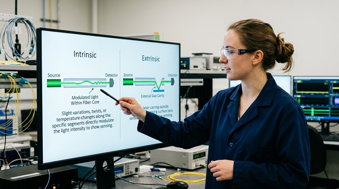
Intrinsic vs Extrinsic Fiber Optic Sensors — What’s the Difference
The difference really comes down to where the sensing actually takes place. In an intrinsic fiber optic sensor, the fiber itself is what does the sensing, and the light never leaves the glass at any point. In an extrinsic one, the fiber only carries light to and from a separate sensing region that sits outside the fiber. That single design choice, which is defined in the standard fiber-optic sensor classification, essentially decides which real-world problem each type is best suited to solve.
When should you pick an intrinsic sensor?
You would generally choose intrinsic when you need to measure something spread out along a long path. Because the fiber is the sensor itself, distributed systems like DTS and DAS can turn one single cable into thousands of measurement points, sensing roughly every centimeter across kilometers of fiber. If a beginner asks how you would monitor 30 km[1] of pipeline for leaks, this is really the answer, since one intrinsic fiber can replace thousands of separate probes.
When is an extrinsic sensor the smarter choice?
You would pick extrinsic when the measurement point is a tiny, harsh, or hard-to-reach spot, which is basically the opposite of the long-path situation described above. The fiber just pipes light in and back out, so the fragile glass itself stays safe while an external cavity handles the actual sensing. And this is why extrinsic designs tend to dominate biomedical probes and factory photoelectric detection in tight spaces, because a small reflective gap can detect the presence of an object or even a beating artery.
| Factor | Intrinsic | Extrinsic |
|---|---|---|
| Sensing element | The fiber itself | External region |
| Best for | Long distributed monitoring | Single-point, tight spots |
| Typical use | Pipeline, power cable | Medical probe, machine part |
How Does Temperature Sensing Work in a Power Cable — A Step-by-Step Example
A distributed fiber optic sensor turns one strand of glass into thousands of thermometers along a power cable. The fiber runs inside the cable jacket. A device called an interrogator fires laser pulses down it, reads the light that scatters back, and maps temperature along the whole route, sensing roughly every centimeter. Utilities use this to catch a hot spot before it melts insulation.
⚠️ Common mistake: Choosing Fiber Bragg Grating sensors when you actually need continuous coverage across kilometers. This happens because FBG offers precise point measurements, so buyers assume “more points” scales cheaply—but each grating adds cost and interrogation complexity. The fix: use distributed sensing for long pipelines or perimeters where thousands of continuous points along one fiber matter more than individual point accuracy.
Here is the chain, step by step. A pulse of laser light travels down the fiber. As it moves, tiny amounts scatter backward. Two kinds matter for heat: Raman backscatter and Rayleigh backscatter.
Raman light comes back in two colors, a Stokes signal and an anti-Stokes signal. The anti-Stokes color grows brighter as the glass gets hotter, while the Stokes color barely moves. The interrogator compares the two and calculates the exact temperature at that point.
How does it know where along kilometers of cable that heat sits? Timing. Light travels at a fixed speed in glass, so the delay before the scattered light returns tells the interrogator the distance, the same principle radar uses. This method is called Distributed Temperature Sensing (DTS).
The practical payoff is early warning. A buried joint that starts overheating shows up as a warm bump on the temperature profile days before it fails. Operators throttle the current or dispatch a crew, no digging blind. That’s why grid operators trust this kind of fiber optic sensor on high-voltage links: it sees trouble across the entire cable, not just at a few probe points.
Fiber Optic Sensor vs Electrical Sensor — Which Should You Choose
Choose a fiber optic sensor when your environment has strong electrical noise, explosion risk, or long distances; choose an electrical sensor when cost and simplicity matter most. The two technologies rarely compete head to head, each wins a different job. Fiber optic sensors are immune to electromagnetic interference (EMI) and safe in high-voltage zones, but they need a pricey interrogator (the box that reads the light). That trade-off decides most projects.
EMI is stray electrical noise from motors, welders, and power lines that corrupts electrical signals. Since fiber carries light, not current, that noise never touches the reading. And because there’s no metal wire at the sensing tip, fiber creates no spark, critical in gas plants or fuel tanks.
| Factor | Fiber Optic Sensor | Electrical Sensor |
|---|---|---|
| EMI immunity | Full — carries light | Needs shielding |
| Explosive/high-voltage zones | Safe, no spark | Risky, needs barriers |
| Distance reach | Tens of km on one fiber | Meters before signal loss |
| Points per line | Thousands (multiplexed) | One per wire pair |
| Upfront cost | High (interrogator) | Low |
Here is the picking rule: if you must monitor a 10 km[2] pipeline, a 400 kV[3] transformer, or a hydrogen line, then pick fiber, because one strand replaces thousands of wired probes. If you need one temperature reading in a quiet control cabinet, then an electrical thermocouple wins on price. So what’s a fiber optic sensor best at? Scaling across distance and surviving hostile environments where copper fails.
What Are the Limitations, Failure Modes, and Cost Realities
The honest answer to what’s a fiber optic sensor’s downside: the fiber is cheap, but the interrogator that reads it is not. A single-mode fiber cable runs a few dollars per meter, yet a distributed sensing interrogator often costs approximately $30,000[4] to approximately $100,000+. Below a certain scale, the math simply doesn’t work, which is why the failure modes and break-even point below matter as much as the physics.
What breaks a fiber optic sensor in the field?
Three failure modes dominate. First, bend loss: coil a standard fiber tighter than its minimum bend radius (often 30mm[5]) and light leaks out of the core, faking a signal drop. Second, connector contamination,a single dust speck on a ferrule end-face can add 3dB of loss, enough to blind a reading. Clean every connector with a fiber wipe before mating. Third, physical breakage: glass fiber snaps under sharp pulls or crush loads, and repairing it needs a fusion splicer, not a screwdriver.
Why does one fiber sometimes give confusing readings?
Because temperature and strain both stretch the fiber, a Bragg-grating sensor can’t always tell them apart. This cross-sensitivity means a cable warming up looks identical to a cable being pulled tighter. Engineers solve it with a second reference fiber that feels temperature but no strain, then subtract. The fiber-optic sensor design must account for this from day one.
When does the investment not pay off?
Skip fiber for single-point measurements in clean, low-noise settings. A $15[6] thermocouple beats a $40,000[7] interrogator when you only need one temperature at one spot. Fiber wins on distributed sensing,thousands of points on one strand,not on replacing a lone gauge.
Where Are Fiber Optic Sensors Used in the Real World
Fiber optic sensors run inside bridges, oil wells, jet wings, and heart catheters. What links these fields? Each one either has strong electromagnetic noise, explosive gas, extreme heat, or needs a probe smaller than a wire, exactly where electrical sensors fail. A distributed fiber can also sense roughly every centimeter along its full length, so one cable replaces thousands of point sensors.
How are they used in bridges and dams?
Engineers glue or embed fiber along a bridge deck to watch strain and cracks in real time. This is called structural health monitoring. Because the glass doesn’t corrode like a metal strain gauge, it survives inside wet concrete for decades. A single fiber down a dam wall tracks seepage temperature and stress at once, one strand doing two jobs.
Why does oil and gas rely on downhole fiber?
Down a well, temperatures top 200°C[8] and pressure crushes electronics. Fiber has no circuit to fry. Operators drop it thousands of feet to map heat and flow along the whole borehole, spotting a leak or a blocked zone from surface readings alone.
Where else does fiber beat electronics?
- Perimeter security: buried fiber senses footstep vibration along kilometers of fence, with no power needed in the field.
- Aerospace strain: lightweight fiber gauges bond onto wings and turbine blades where weight and lightning strikes rule out metal wiring.
- Medical probes: because they’re tiny and immune to electromagnetic interference, fibers measure arterial pulse waves and work safely inside an MRI scanner.
So when you ask what’s a fiber optic sensor good for, the answer is any place too hot, too electric, too tight, or too remote for a normal sensor.
Frequently Asked Questions About Fiber Optic Sensors
Short answers to the questions people ask most about what’s a fiber optic sensor, how it performs, and what happens when things go wrong. Each answer sticks to facts you can act on.
Can a fiber optic sensor measure multiple points on one cable?
Yes. Distributed sensing methods like DTS and DAS turn the fiber itself into a continuous sensor, giving sensing points about every centimeter along the full length. One 10 km[9] fiber can act as tens of thousands of separate measurement points, so you skip installing thousands of individual probes.
Do they need electricity at the sensing point?
No. The sensing tip is passive glass with no wires or power. All the electronics, the light source and detector, sit at the far end, sometimes kilometers away. That’s why these sensors work safely inside fuel tanks, explosive zones, and high-voltage gear.
How accurate are they?
Very. A well-calibrated distributed temperature sensor holds ±1 °C[10] over long distances, and strain systems resolve microstrain (one millionth of a length change). Because light-based readings ignore electromagnetic interference, accuracy stays stable in noisy electrical environments where copper sensors drift.
Can they be repaired if the fiber breaks?
A broken fiber gets fusion-spliced, the two ends are melted together, adding only a tiny signal loss of about 0.02 dB. Splicing needs a trained technician and a fusion splicer, but the rest of the cable keeps working. See the fiber-optic sensor overview for more.
Key Takeaways and Where to Learn More
The core answer to what’s a fiber optic sensor comes down to one image: light is the messenger. You send light down a glass or plastic fiber, the thing you measure bends, delays, or dims that light, and a detector reads the change. Master that model and every variant makes sense.
Three decisions guide your build. First, intrinsic vs extrinsic: the fiber itself senses (intrinsic) when you need thousands of measurement points along one strand, or the fiber just carries light to a remote sensing tip (extrinsic) when you need a single precise spot. Second, fiber vs electrical: pick fiber for strong electromagnetic noise, explosive gas zones, or heat above 200°C, where fiber’s immunity to electromagnetic interference beats copper. Third, point vs distributed: distributed sensing (DTS or DAS) turns one fiber into a continuous sensor with a reading roughly every centimeter along its full length, while a point sensor watches one location.
Your next step is a scope question. Ask: do I need to know where something happens, or just that it happens? A leaking 5-kilometer pipeline needs distributed sensing to pinpoint the breach. A single motor bearing needs one point sensor.
For deeper technical grounding, the Wikipedia entry on fiber-optic sensors defines the intrinsic and extrinsic split clearly. From there, map your measurand, environment, and spatial resolution before you request quotes from suppliers.
Reference Sources
- [1]en.wikipedia.org/wiki/Fiber-optic_sensor — supports: A fiber-optic sensor is a sensor that uses optical fiber either as the sensing element (…
- [2]baumer.com — supports: Industrial fiber optic sensors commonly use an LED light source and a photodiode receive…
- [3]keyence.com — supports: Commercial fiber optic photoelectric sensors are widely used in factory automation to de…
- [4]rp-photonics.com — supports: Fiber-optic sensors can measure physical quantities such as temperature, strain, pressur…
- [5]viavisolutions.com — supports: Distributed fiber optic sensing technologies such as DTS, DTSS, and DAS use the fiber it…
- [6]metrol-sensor.com — supports: Fiber optic sensors are immune to electromagnetic interference and can operate reliably …
- [7]lunainc.com — supports: The basic fiber-optic sensing system consists of a light source (often a laser or LED), …
- [8]sciencedirect.com — supports: Modern biomedical engineering applications use fiber optic sensors for measuring movemen…
- [9]hifieng.com — supports: In distributed fiber optic sensing, continuous measurement along the full length of the …
- [10]wikipedia.org — supports: General definition, intrinsic vs extrinsic classification, and overview of fiber-optic s…




