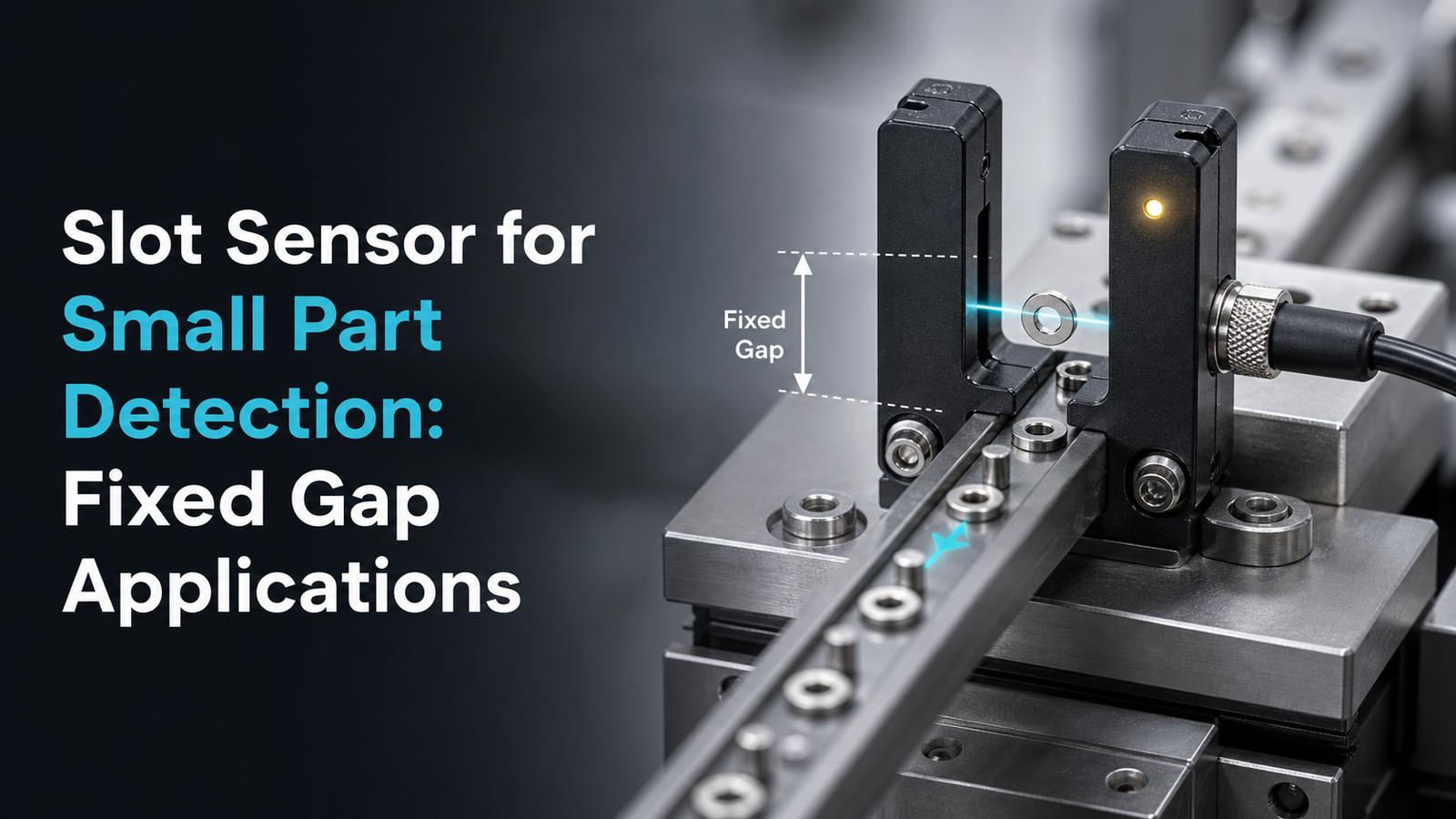
Slot sensor small part detection uses a fork-shaped device that projects a light beam across a fixed U-shaped gap, triggering the moment a part breaks that beam. Banner Engineering’s SLM Series rugged metal slot sensor detects objects as small as 0.30 mm[1] passing through the slot, with response times under 1 ms for high-speed counting (Banner Engineering, 2026). Because emitter and receiver sit on fixed arms, there’s zero alignment work, unlike standard through-beam photoelectric pairs. Slot widths typically range from 2 mm to 220 mm.
This guide answers the questions buyers actually tend to ask. How does a slot sensor differ from a through-beam pair? What parts really make up the fixed-gap housing? And which specifications, the slot width, the minimum detectable object, and the response time, should decide what you pick? On top of that, where do these sensors beat other detection methods out on the line?
Quick Takeaways
- Fixed U-shaped gap eliminates emitter-receiver alignment work entirely.
- Top slot sensors detect parts down to 0.30 mm.
- Sub-1 ms response times enable high-speed part counting.
- Choose slot width between 2 mm and 220 mm.
- Pick metal-housing models to resist vibration and coolant.
What’s a slot sensor and how does it detect small parts in a fixed gap?
A slot sensor is a fork-shaped light-based device that puts its light sender and its light catcher on two fixed arms that face each other across a set gap. When a part passes through that gap and blocks the beam, the sensor fires off a signal instantly. Some models can pick up objects as tiny as 0.30 mm (2026), which is what makes dependable slot sensor small part detection possible on fast counting lines. Because both light parts sit at a known distance apart inside the U-shaped housing, also called a fork, the light really travels the same locked path on every single cycle.
That fixed shape gets rid of the biggest source of error you find in standard light-based sensors, which is drift from a misaligned reflector or a moving target background. It also means you never need a separate reflector at all.
Why does the fixed emitter-receiver geometry improve repeatability?
Fixed geometry means the beam distance never changes, so the trigger point stays consistent part after part after part. A miniature slot sensor can reach switching frequencies of up to 5 kHz (2026) while still detecting objects down to 0.8 × 1.8 mm[2] inside a 5 mm fork. At that kind of speed, the sensor is essentially reading roughly 5,000 parts every second.
- Emitter: an infrared or laser LED sends a narrow, focused beam straight across the fork.
- Receiver: a photodiode watches for the beam being lost and turns that into a switching signal in ≤1 ms.
- Slot (gap): the fixed opening, which is commonly 5, 10, or 20 mm, sets the spot where the part actually has to pass.
How does slot width and beam diameter set the minimum detectable part size?
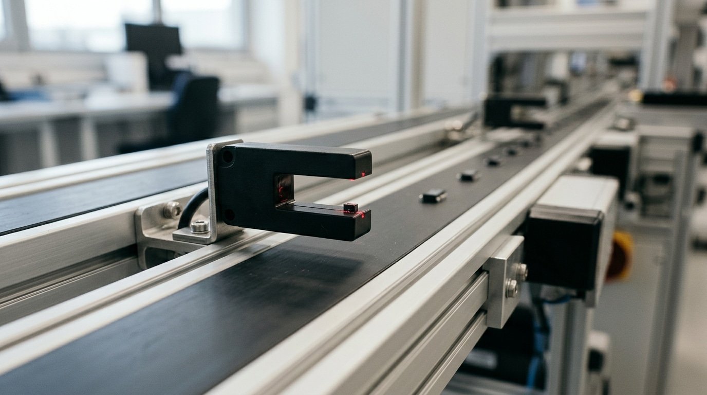
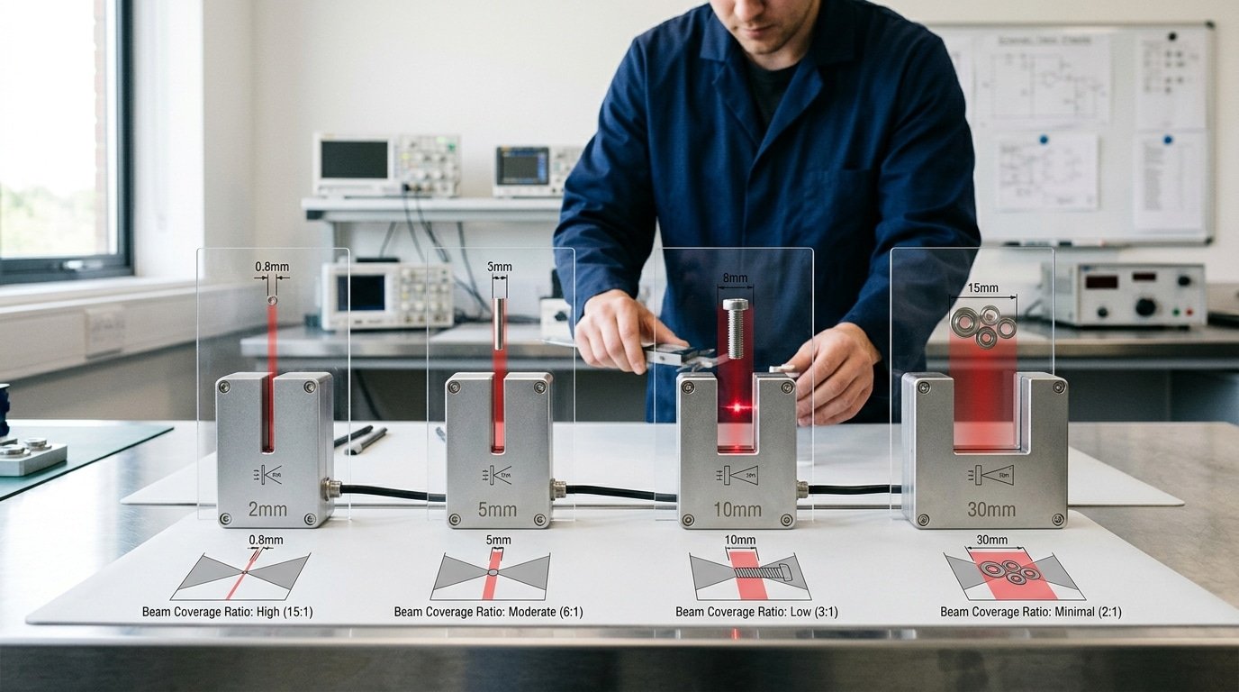
Slot width sets the beam diameter, and beam diameter sets the smallest part you can reliably catch. A 5mm slot in the Pepperl+Fuchs GL5 miniature slot sensor uses an integrated aperture to shrink its beam and detect objects down to 0.8 × 1.8 mm (2026). Narrow the aperture, and slot sensor small part detection reaches sub-millimeter sizes.
Here is the rule that matters: the part must block a meaningful share of the beam cross-section for the receiver to register a change. Engineers call this the beam-coverage ratio. A good target is that the part interrupts at least 30,approximately 50% of the beam. Below that, the signal drop is too small to trip the output.
| Slot width | Typical effective beam | Smallest reliable part |
|---|---|---|
| 2 mm[3] | 0.5–1 mm (apertured) | 0.3 mm |
| 5 mm | 1–2 mm | 0.8 mm |
| 10 mm | 3–5 mm[4] | 2 mm |
| 30 mm | 10–15 mm | 6 mm |
A wide 30mm slot spreads its light across a large area. A 0.5mm[5] chip passing through blocks under 2% of that beam, invisible to the sensor. That’s why laser slot models detecting parts down to 0.8 mm rely on collimated beams and tight apertures, not raw slot size.
Practical tip: pick the smallest slot that still clears your part mechanically. Extra clearance costs you resolution every time.
Which sensor should you pick for sub-millimeter parts — slot, fiber-optic, vision, or capacitive?
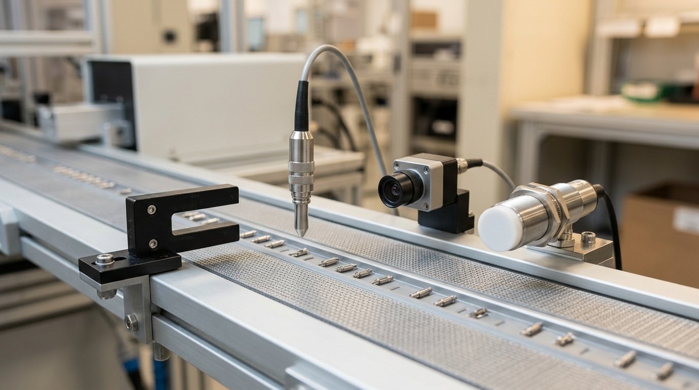
When you have rigid parts smaller than 1 mm that move faster than 1 m/s, a slot sensor is the way to go. It holds the distance between the beam and the part fixed by physical design, so even very small objects stay in focus when the feeder is running quickly. Laser slot sensors can detect parts down to 0.8 mm (2026), and some models can pick out something as small as 0.30 mm, which is finer than what most fiber-optic tips can keep lined up.
The decision really comes down to two factors, which are the material the part is made of and how fast the feeder is running. Metal and opaque plastic show up clearly on optical sensors. Glass and clear plastic call for a capacitive or laser method instead, because light passes straight through them. Below roughly 1 m/s, vision systems do the job and can also check the shape of each part. Above that speed, only slot and laser sensors can keep up without the image blurring from motion.
| Sensor type | Smallest part | Best material | Relative cost | Max feed speed |
|---|---|---|---|---|
| Slot sensor | 0.30 mm | Metal, opaque | Low–medium | >3 m/s |
| Fiber-optic | ~1 mm | Metal, plastic | Low | ~2 m/s |
| Vision | <0.1 mm[6] (with optics) | Any | High | <1 m/s |
| Capacitive | ~2 mm | Glass, liquid | Medium | <1 m/s |
Here is one useful tip from the field. For slot sensor small part detection on vibratory feeders, pick a switching frequency, which is how many times per second the sensor can flip between detecting and not detecting, of at least 5 kHz. That extra margin keeps you from missing counts when parts bunch together or bounce around. It is best to leave capacitive sensors out of this situation, because they wander with changes in humidity and cannot match how quickly a slot sensor responds, which is under 1 ms.
Why do transparent, reflective, or dark small parts cause detection failures?
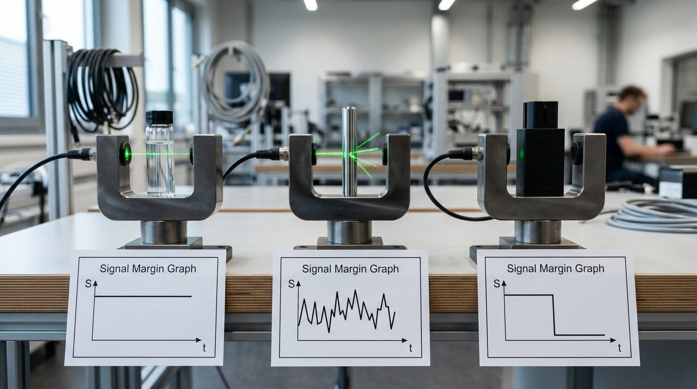
Transparent, reflective, and dark parts fail for a reason that comes down to how each one disrupts the amount of light the sensor has to work with. Clear parts let most of the beam pass straight through, shiny parts scatter it away from the receiver, and dark parts simply absorb it. All three of these shrink what you might call the signal margin, which is the gap between “part present” and “part absent”, until the point where the sensor just can’t tell the two states apart anymore. The way to fix this is matching your optics and gain to the material itself, not buying a more powerful emitter.
How does each material type break the signal?
A transparent part, say a glass vial or a clear plastic pin, might block only 5,approximately 15% of the beam. The receiver still sees plenty of light coming through, so the switching threshold never actually trips. A polished metal shaft behaves like a tiny mirror, bouncing the beam off to the side and away from where it needs to go. And a matte-black connector housing can absorb over 90% of visible light, which mimics a permanent “blocked” state and ends up causing false triggers on the next clear cycle.
What countermeasures actually restore margin?
- Polarized optics: A pair of polarizing filters rejects the scattered glare coming off shiny parts, so only the light on the direct path reaches the receiver.
- Gain and threshold tuning: You lower the switching threshold to catch the small drop caused by transparent parts, and teach-in modes will set this automatically for you.
- Wavelength selection: Infrared emitters, like the infrared LED slot sensors used for high-speed counting, tend to penetrate some tinted plastics better than red light does.
For slot sensor small part detection on mixed materials, a laser-class model that detects down to 0.8 mm gives you extra margin headroom, according to Balluff’s 2026 photoelectric slot sensor documentation. It’s generally worth skipping the general-purpose sensor here. Figure out the material first, then choose accordingly.
What optical specifications matter most for small part detection accuracy?
Response time and light margin matter most for slot sensor small part detection accuracy. A sensor with a 20µs response time can catch a part moving at 3 m/s, while a stable light margin above 1.5x prevents dropouts from dust or vibration. Together they decide whether you catch every part or miss one in a thousand.
⚠️ Common mistake: Choosing a slot sensor with a 30 mm[7] gap to detect 0.30 mm parts “with room to spare.” This happens because wider slots seem more forgiving, but a part far smaller than the beam width can slip through without fully breaking it, causing missed counts. The fix: match slot width tightly to your part path—pick the narrowest gap that still clears your product reliably.
Response time is how fast the output switches after the beam breaks. On a fast-indexing feeder cycling at 2,000 parts per minute, each part blocks the beam for under 100µs. A 20µs sensor sees it. A 1ms sensor misses it entirely. Some slot sensors reach switching frequencies up to 5 kHz, meaning they can register 5,000 edges per second.
Light margin is the ratio of received light to the minimum needed to switch. Below 1.5x, small parts and grime push the signal into the gray zone, causing false triggers. Aim for margin above 3x on clean lines and above 1.5x on dusty feeders.
- Hysteresis: the gap between on and off thresholds. Wide hysteresis stops output chatter on jittery parts, but too wide misses thin edges.
- Repeatability: how consistently the switch point lands. Sub-microsecond repeatability keeps position counts accurate over millions of cycles.
Check hysteresis on the datasheet before you buy. A sensor with tight repeatability but no hysteresis margin will double-count vibrating parts. Learn more about photoelectric sensor response behavior.
How are slot sensors used in semiconductor and packaging fixed-gap lines?
Slot sensors run these lines because the parts arrive in a fixed, known position every time, so the beam only has to answer one question: is the part there or not? A miniature slot sensor built for semiconductor work detects objects down to 0.8 × 1.8 mm at a 5 mm fork width, switching up to 5 kHz (2026). That speed lets it count parts flying past faster than the eye can track.
Here is where slot sensor small part detection earns its keep on real lines:
- Lead-frame edge counting: the thin metal strip that holds an IC’s pins passes through the slot; each edge break increments the count, confirming no strips are skipped or stuck.
- IC tray slot verification: the sensor checks that each pocket in a JEDEC tray holds a chip before the pick-and-place arm moves, catching empty slots that would jam downstream.
- Blister pack pill presence: the beam crosses each cavity to confirm a tablet sits inside before the foil seals it.
- Capsule counting: on a vibratory feeder, capsules drop single-file through the fork, and each interruption adds one to the fill total.
The fixed gap wins here because the part always crosses the same spot at the same height, no focusing, no re-teaching per lot. That repeatability keeps miscounts low on pharmaceutical fill lines, where regulators expect near-zero fill errors under FDA cGMP rules. That repeatability, though, depends on holding the beam steady when the feeder shakes, the next section covers mounting these sensors on high-speed feeders without vibration errors.
How do you mount, align, and compensate for vibration on high-speed feeders?
Mount the slot sensor on a rigid bracket bolted directly to the feeder frame, center the beam on the exact part path, and add 1,3 ms of debounce timing to reject vibration noise. On vibratory bowl feeders running above 500 parts per minute, this combo cuts false triggers while keeping every real part counted.
Why does rigid bracket mounting beat flexible mounts?
A rigid bracket keeps the beam from shifting when the bowl shakes. Vibratory feeders oscillate at 50,120 Hz, and any flex lets the beam drift off the part path. Bolt the sensor to a machined aluminum block, not a thin sheet-metal tab. Then dampen the mount with a rubber isolation pad to absorb residual shake.
How do you align the beam and stop false counts?
Center the beam on the part path, not the slot center. Parts often ride one side of the track. Sensors like the Pepperl+Fuchs GL5 detect objects down to 0.8 × 1.8 mm at a 5 mm fork width with 5 kHz switching, so a misaligned beam of even 0.5 mm can miss a small part entirely.
Debounce timing filters out double-counts. Set it just below the fastest real part gap. At 500 parts/minute, parts arrive every 120 ms[8], so a 2 ms debounce window is safe. Re-check alignment weekly; feeder wear shifts the track over time.
What mistakes cause slot sensors to miss or double-count small parts?
The four biggest mistakes are an oversized slot for tiny parts, a dirty lens that eats light margin, the wrong response mode, and part edge chatter that triggers double counts. A slot rated for 5 mm passing a 0.3 mm chip leaves a huge beam the part barely blocks, light margin drops below the threshold and the count vanishes. Sensors like the SLM Series detect parts as small as 0.30 mm only when the slot is matched to the part.
Work the diagnosis in order. Skip guessing, measure.
- Missed parts: Check light margin first. If it reads under 2× with a clean slot, the beam is too wide for the part. Add an aperture or drop to a narrower fork.
- Intermittent drops: Wipe the lens with lint-free cloth. Oil mist and dust cut received light 30–approximately 50% within weeks on vibratory feeders, quietly shrinking your margin until borderline parts fall through.
- Double counts: A rough or tumbling part edge crosses the beam twice. Enable output hysteresis or a minimum-on-time filter (1–3 ms) so one part registers once.
- Erratic timing: The wrong response mode. Fast parts need light-operate with short response time; slow presence checks need dark-operate hold.
For slot sensor small part detection at high feed rates, the fix is almost always mechanical or optical, not the controller. Confirm alignment and margin before you touch code.
Frequently asked questions about slot sensors for small part detection
The smallest part a slot sensor reliably catches is 0.3 mm. Banner Engineering’s SLM Series detects objects down to 0.30 mm passing through the fork (2026 spec). Below that, switch to fiber-optic or laser slot models rated to 0.8 mm[9] minimum for stable margin.
Can slot sensors detect clear plastic parts?
Yes, but only with the right model. Standard infrared slot sensors struggle with clear plastic because light passes straight through, leaving only a 5,approximately 15% signal drop. Use a laser-based slot sensor instead, its focused beam picks up the small refraction and edge shadow that clear parts create. Set a tighter switching threshold, and clean the emitter lens often. Even a thin dust film costs you the light margin these transparent parts need.
How is a slot sensor different from a through-beam sensor?
A slot sensor is a through-beam sensor built into one U-shaped body. Both use a separate emitter and receiver facing each other. The difference is alignment: a through-beam pair needs manual setup across an open gap, while the slot version fixes the emitter and receiver at a locked distance inside the fork. That factory alignment is why slot models hit sub-millimeter accuracy on fast feeders.
What do slot sensors cost?
Basic optical slot sensors run roughly $40 to $150. Precision laser and semiconductor-grade units, like those rated for 0.8 × 1.8 mm parts at 5 kHz switching, reach $200 to $500. Response time drives the price, sub-millisecond models cost more than 1 ms units. See the photoelectric sensor overview for how these categories relate.
Choosing the right slot sensor for your small-part application
Start with your smallest part, then work backward to slot width and sensor type. A rigid metal part at 0.30 mm[10] needs a rugged metal-housing slot sensor, while a 0.8 mm part on a semiconductor line pairs well with a laser or aperture-equipped fork. The SLM Series metal slot sensor handles objects down to 0.30 mm in counting and conveyor jobs, which sets the practical floor for reliable slot sensor small part detection.
Three inputs decide everything: part material, part size, and line speed. Material tells you if a standard beam works or if you need a laser for glossy, dark, or clear parts. Size fixes the maximum slot width you can tolerate. Speed sets your response-time budget.
What checklist should you run before buying?
Measure and lock these five numbers before you request a quote:
- Smallest part dimension: pick a sensor rated at least 30% below it (0.30 mm floor for metal forks).
- Slot width: choose the narrowest fork that still clears your part path — 5 mm suits sub-millimeter components.
- Line speed: convert parts-per-minute to required response time; a 5 kHz switching frequency handles very fast feeders.
- Material behavior: flag transparent or reflective parts early — they need laser or high-margin models.
- Output type: match PNP/NPN and IO-Link to your controller.
Never commit on a datasheet alone. Request physical samples and test them with your actual parts on your feeder speed. Ask suppliers for spec sheets showing minimum detectable object size at your fork width, plus light-margin curves. A one-week bench trial catches material and vibration failures that no spec page reveals.
See also
Can inductive sensors detect aluminum without losing accuracy
Slot type photoelectric sensor
How Capacitive Sensors Detect Plastic Objects Reliably
Why Nominal Range Misleads Buyers on Sensor Reach
How does a proximity sensor work and where is it used




