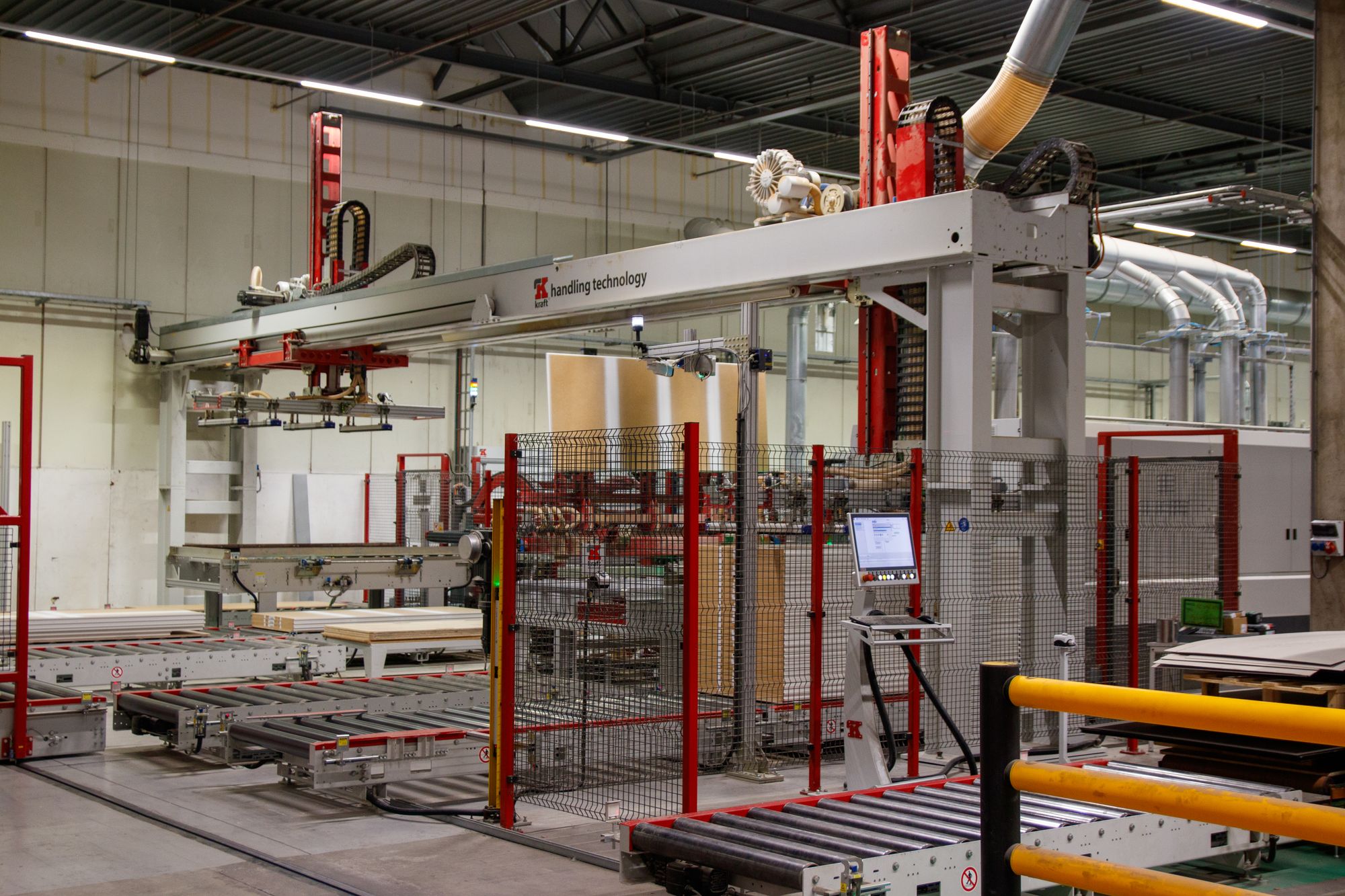
Photoelectric sensor commissioning guide
How to Align a Photoelectric Sensor in 7 Proven Steps
Align the optical path, center the stable detection window, tighten without shifting the bracket, and validate with the real target, background, speed, and environment. This method covers through-beam, retroreflective, diffuse, and background-suppression sensors.
- Center the stable optical window
- Separate alignment from sensitivity problems
- Validate worst-case production conditions
The short answer
Do not stop when the output LED first changes. Move the emitter, receiver, or reflector across the horizontal and vertical acceptance limits, then secure the assembly near the center of the stable region. For diffuse and background-suppression sensors, teach or adjust with the actual target and background instead of aiming at an empty space.
A successful alignment must remain stable after tightening and during real production, not only during a static bench test.
What good alignment achieves
Alignment is more than making the output switch once
A sensor may switch during setup yet fail later because the optical path sits near an acceptance edge, the bracket moves during tightening, or the real target differs from the setup target. Build margin into the complete installation.
Optical stability
Position the optical path within the model's stable reception or teach window, using its specified indicators, display, or commissioning procedure.
Mechanical stability
Use a rigid mounting surface, controlled cable routing, and a tightening sequence that does not rotate the sensor or reflector.
Process stability
Test the smallest, darkest, fastest, most reflective, or least repeatable target expected in production, plus the real background.
Safety and preparation
Control machine motion before touching the sensor
Photoelectric alignment normally requires a powered sensor, but it must not expose the technician to hazardous motion. Follow the machine's commissioning and hazardous-energy-control procedure. Make wiring changes only with power removed, then use the site's controlled test mode when optical checks require power.
- Confirm the exact model, sensing mode, supply voltage, output logic, wiring, and indicator meanings.
- Use the specified reflector for retroreflective models and the real target for diffuse or background-suppression models.
- Clean the sensor lens and reflector with a method compatible with their materials.
- Inspect brackets, fasteners, cable strain relief, connector seating, and the sensing path.
- Prevent nearby emitters, reflective guards, tools, hands, and machine parts from entering the beam during setup.
Standard photoelectric sensors are not personnel-protection devices. Use a safety-rated device and validated safety function where human protection is required.

First decision
Select the sensing mode before choosing the alignment method
Through-beam and retroreflective sensors are aligned around an optical path. Diffuse and background-suppression sensors are adjusted around the target and background response. Use the selector to see the correct reference for each method.
Which sensor are you aligning?
Center the emitter inside the receiver's stable acceptance window
Align the emitter and receiver at their final distance. Sweep one axis at a time to find the stable on/off limits, then position near the middle and recheck after tightening.
Center the beam on the correct reflector
Install the specified reflector at the final location, aim the sensor at its usable center, and confirm the target fully interrupts the returned light. Polarized models help reject many shiny targets, but still require an application test.
Adjust with the actual target at the actual distance
A diffuse sensor depends on light returned by the target. Use the smallest or darkest expected target, verify all presentation angles, and confirm that the real background does not trigger the output.
Teach the target and the background as separate states
Background-suppression sensors use optical geometry to separate distances. Aim at the target zone, teach or set the switching point according to the model, and validate both states with the closest background and farthest acceptable target.


The complete procedure
Seven steps to align a photoelectric sensor correctly
Complete the steps in order. Each one has an observable acceptance condition, so commissioning does not depend on guesswork or a single LED change.
-
Identify the sensing mode and define the two required states
Read the exact model instructions. Record whether the sensor is through-beam, retroreflective, diffuse, or background suppression; whether the output is light-on or dark-on; and what each LED, display value, or teach indication means.
Write the required process states before adjusting anything: for example, "output off with a clear beam" and "output on when the smallest package blocks the beam." This prevents a correct optical alignment from being mistaken for an output-logic fault.
Pass whenThe technician can name the sensing mode, output logic, target state, clear state, and model-specific stability indication.
-
Build a rigid, repeatable mechanical reference
Mount the sensor, receiver, or reflector on a surface that does not flex during normal vibration, washdown, guarding movement, or cable motion. Start with fasteners snug enough to hold position but loose enough for controlled adjustment.
Route the cable so it does not twist the housing. Confirm that the final guard, bracket, and product guide positions will not clip the beam.
Pass whenThe optical components hold their approximate aim without hand support, and cable movement does not rotate the sensor.
-
Clean the optics and place the real reference at final distance
Clean the emitting window, receiving window, and reflector. Install the specified reflector for retroreflective sensing. For diffuse or background-suppression sensing, use the real target and real background at their final distances.
Begin with the smallest, darkest, most angled, or otherwise least reflective acceptable target if those conditions vary. A bright setup card can hide a weak real application.
Pass whenOptical surfaces are clear and the setup reference represents the hardest acceptable production condition.
-
Power the sensor under a controlled commissioning state
With hazardous machine motion controlled according to the site's procedure, energize the sensor and verify supply status, output status, and any stability, alignment, teach, or signal indication. Do not assume an LED color has the same meaning across manufacturers or models.
If the sensor has no power indication, unstable supply, incorrect wiring, or a shorted output, correct that condition before optical alignment.
Pass whenPower and wiring are confirmed, and every indicator is interpreted from the exact model documentation.
-
Find the stable window on both axes and move to its center
For through-beam and retroreflective sensors, sweep slowly left to right until the stable signal is lost at each side. Position near the midpoint, then repeat vertically. If both the emitter and receiver can move, stabilize one reference before adjusting the other.
For diffuse or background-suppression sensors, follow the model's teach or sensitivity sequence with the target and background. The correct setting is a stable separation between both states, not simply maximum sensitivity.
Pass whenA repeatable stable region exists on both axes, or the taught target and background states remain clearly separated.
-
Tighten incrementally without moving out of the window
Tighten fasteners in small alternating increments while watching the model's signal or stability indication. Recheck horizontal and vertical margin after final torque. A bracket can rotate enough during tightening to move a long-distance beam off center.
Mark the final bracket position where useful. If repeat adjustments are common, improve the bracket or add a positive mechanical reference instead of relying on repeated visual aiming.
Pass whenFinal torque is applied and the stable indication remains unchanged after light pressure is removed from the assembly.
-
Validate every real operating state and record the baseline
Run the process at normal speed with the full acceptable target range. Test the clear path, target present, gaps, leading and trailing edges, reflective backgrounds, neighboring sensors, guards, and expected ambient-light conditions. Include contamination or washdown states when they are part of the application.
Record the final position, teach value or signal indication, model settings, target used, and test result. That baseline makes future troubleshooting faster and reveals mechanical drift or optical contamination.
Pass whenThe output remains correct across all approved target and no-target states at production speed, with no unexplained chatter or missed detections.
Through-beam alignment
Use the two signal-loss edges to find the optical center
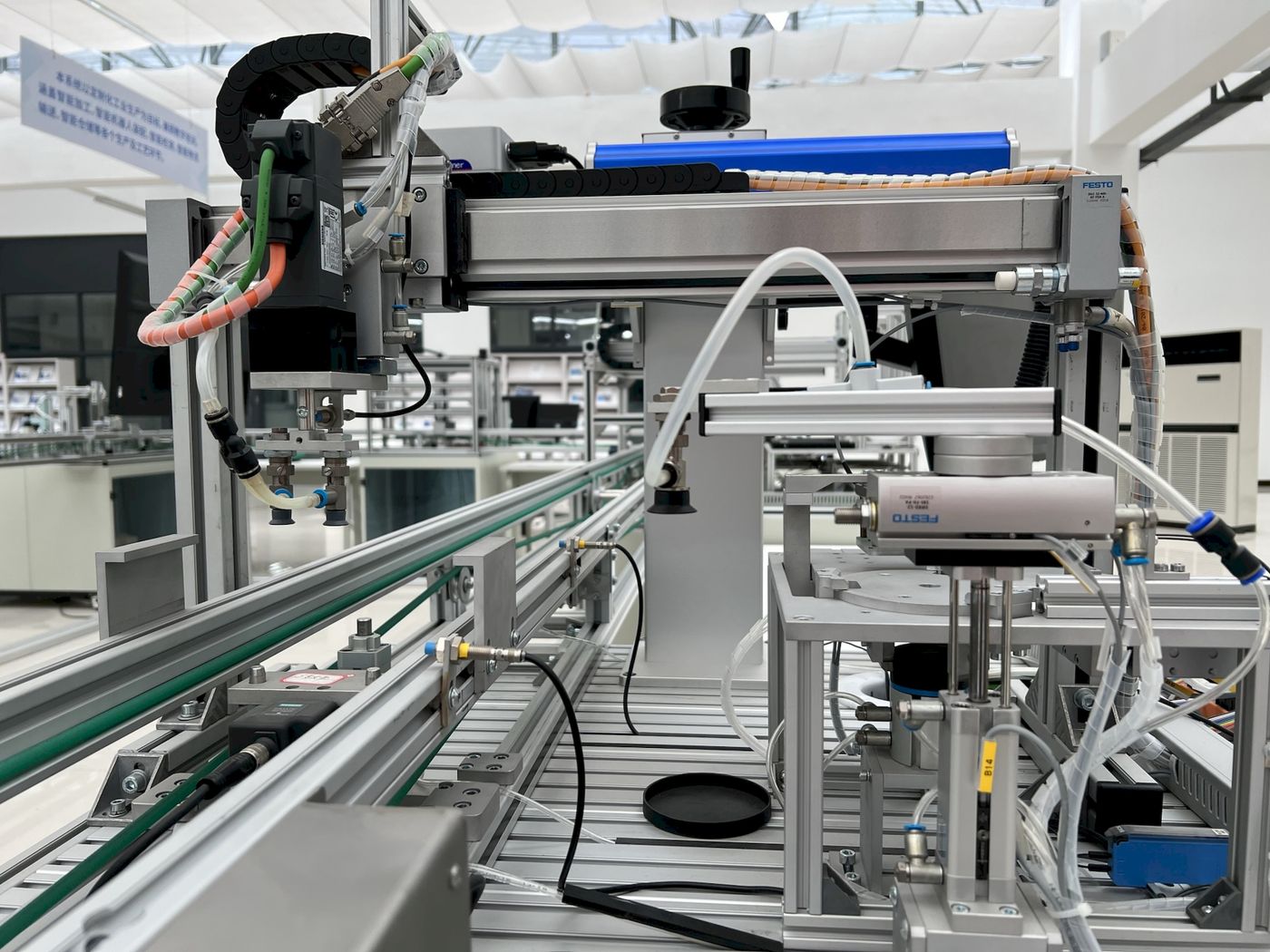
A through-beam pair has separate emitter and receiver housings. After rough aiming, slowly sweep one component through the reception zone. Note where the model's stable signal is gained and lost, position in the middle, and repeat on the second axis.
- Align at the final operating distance and bracket height.
- Keep the complete beam path clear, not only the visible center point.
- Check that adjacent emitters cannot enter the wrong receiver.
- Test that the smallest target blocks enough of the effective beam.
The exact acceptance width depends on the model and distance. The goal is the center of the measured stable window, not a universal mounting angle.
Retroreflective alignment
Aim at the usable center of the specified reflector
Retroreflective sensors emit and receive from one housing. A compatible reflector returns the beam. Mount the reflector flat and stable, aim the beam toward its center, and sweep horizontally and vertically to find the stable return region before tightening.
The target must interrupt the effective beam, not merely pass through a visible spot. Small targets may require a smaller beam, a different optical arrangement, or a through-beam sensor. Highly reflective targets can return light like a reflector; a polarized retroreflective model is often selected for this case, but the actual target still needs testing.
Do not substitute reflectors casually. Reflector geometry, size, sensing distance, polarization behavior, and operating reserve are model-specific. Use the sensor manufacturer's compatible reflector data.
Diffuse and background suppression
Teach the process states, not an ideal sample
Diffuse sensing depends on returned light, so target color, gloss, angle, size, and distance can change the result. Background-suppression models add distance discrimination, but their switching point and usable target range still require an application-specific setup.
Present the hardest target
Place the least reflective acceptable target at its farthest or most difficult expected position. Find the model-specific target detection or teach point.
Present the closest background
Remove the target and place the real background in its closest expected position. Find the model-specific background response or teach state.
Set and prove the separation
Follow the manufacturer's teach or sensitivity procedure, then verify stable target detection and stable background rejection across all approved variations.
If no stable setting separates target from background: alignment alone will not solve the application. Increase distance separation, change the mounting geometry, reduce background reflectivity, or select background suppression, through-beam, retroreflective, fiber optic, or another suitable sensing principle.
Operating reserve and indicators
There is no universal LED color or reserve multiplier
Operating reserve, also called excess gain on some data sheets, compares received light with the switching threshold. The useful margin and the way it is displayed depend on the exact sensor, distance, target, reflector, sensitivity setting, and environment.
What the ratio means
Received signal / switching thresholdA value at the switching threshold has little practical margin. The required reserve above that point must come from the manufacturer's curve, indicator definition, or application guidance for the exact model.
Interpret power, output, stability, alignment, teach, and signal LEDs from the exact instruction sheet. Green, yellow, blue, and red do not have universal meanings.
Center the optical path or teach a clean target/background separation. Do not increase diffuse sensitivity until the background also triggers.
Save the signal value, teach result, stability indication, or documented adjustment position. Future deviation can then be linked to contamination, movement, damage, or process change.
Fast fault isolation
When alignment does not stop false triggers
Use the symptom to separate optical alignment from wiring, output logic, interference, target contrast, background, response, or mechanical faults.
| Symptom | Likely cause | Decisive check | Corrective action |
|---|---|---|---|
| No indicator or output | Supply, connector, wiring, short circuit, or wrong pinout | Measure voltage at the sensor under load and compare wiring with the exact model diagram | Correct power and wiring before optical adjustment |
| Switches only at one bracket position | Optical path sits near the acceptance edge | Sweep horizontally and vertically and mark both stable limits | Move to the center and strengthen the mounting reference |
| Stable until fasteners are tightened | Bracket rotation, uneven clamping, or cable torque | Watch the model's signal indication while tightening incrementally | Change tightening order, bracket rigidity, or cable routing |
| False output with no target | Background reflection, nearby emitter, ambient light, or excessive sensitivity | Block one possible source at a time and compare the clear-state signal | Re-aim, shield, separate channels, use anti-interference functions, or change sensing mode |
| Shiny target is missed | Retroreflection from the target reaches the receiver | Rotate or translate the target while monitoring output and stability | Evaluate polarized retroreflective, through-beam, or alternate geometry |
| Dark or small target is missed | Insufficient returned light, large effective beam, or target outside the taught range | Test the worst-case target at the farthest approved position | Re-teach, reduce distance, change angle, or choose a better-suited optical mode |
| Random chatter during machine motion | Vibration, cable fault, intermittent blockage, or process bounce | Observe bracket, cable, target path, signal, and PLC input at production speed | Fix the mechanical cause; apply model-specific filtering only after the cause is understood |
| Correct sensor LED, wrong PLC state | NPN/PNP, light-on/dark-on, NO/NC logic, input common, or program logic mismatch | Compare sensor output voltage and PLC input state for target and clear conditions | Correct wiring, configuration, or logic rather than re-aiming the optics |
Commissioning acceptance
Complete this final alignment validation
Check each item with the machine in its controlled commissioning state. A complete result means the sensor has been tested as part of the process, not only as a standalone device.
Keep the alignment reliable
Use condition-based checks instead of an arbitrary cleaning interval
Inspection frequency should reflect dust, oil mist, washdown, vibration, temperature cycling, production criticality, and the sensor manufacturer's guidance. Use the commissioning baseline to detect change.
Inspect contamination
Clean lenses and reflectors with approved materials when signal margin or the process environment indicates the need.
Check movement
Look for impact marks, loose fasteners, bent brackets, cable torque, and guard movement around the optical path.
Check connections
Inspect connectors, cable damage, supply quality, grounding practices, and PLC input behavior before changing sensitivity.
Review target changes
Revalidate when product color, size, packaging, speed, background, guides, or nearby sensors change.
Still seeing missed counts or unstable switching?
Send XSZ the sensor model, sensing distance, target material and size, background distance, mounting photo, supply/output details, and a short description of the failure state. We can help separate alignment, application, wiring, and model-selection issues.
Continue the selection process
Related photoelectric sensor resources
Use these pages to compare sensing modes and choose a more suitable optical arrangement when alignment alone cannot create a stable process window.
Frequently asked questions
Photoelectric sensor alignment FAQ
How do I know when a photoelectric sensor is aligned correctly?
Correct alignment means the model's stable reception or teach indication remains valid after final tightening and during all approved target, background, speed, and environmental states. A single output transition during setup is not enough.
Should I set a photoelectric sensor to maximum sensitivity?
Not automatically. Maximum sensitivity may help some through-beam applications, but on diffuse sensors it can also detect the background. Follow the exact model procedure and prove stable separation between the required target and no-target states.
What do the green, yellow, red, or blue LEDs mean?
LED meanings are not universal. Depending on the model, they may indicate power, output, stable reception, teach status, fault, signal strength, or alignment quality. Use the exact product instruction sheet.
How do I align a through-beam photoelectric sensor?
Mount the emitter and receiver at final distance, sweep across the stable reception limits horizontally, center the position, repeat vertically, tighten gradually, and validate clear-beam and blocked-beam states with the real target at production speed.
How do I align a retroreflective photoelectric sensor?
Install the specified reflector at its final position, aim the sensor toward the reflector center, sweep both axes to find the stable return window, tighten without movement, and confirm that every real target fully produces the required output state.
Why does the sensor work by hand but miss products on the conveyor?
The setup object may be larger, slower, brighter, or positioned differently from the product. Test the smallest, darkest, fastest, and most angled approved target while the conveyor, guides, guards, background, and nearby sensors are in their final operating state.
Why does alignment change when I tighten the bracket?
Fastener torque can rotate a flexible bracket or shift the housing, and cable routing can add torque. Tighten in small alternating increments while monitoring the stability indication, then improve the bracket or cable strain relief if movement continues.
Can nearby photoelectric sensors interfere with each other?
Yes. A receiver may see light from a neighboring emitter, especially when optical paths are close or parallel. Increase spacing, alternate emitter/receiver orientation where appropriate, use shielding or the model's anti-interference function, and verify the arrangement with all sensors energized.
When should I change the sensing mode instead of realigning?
Change the optical method when no stable window separates the target from the background, the target does not block enough of the beam, reflective targets defeat the selected mode, the required distance exceeds the model's verified range, or the environment cannot preserve the optical path.
Technical references
- OMRON: Setting the optical axis of a through-beam photoelectric sensor
- OMRON: Preventing mutual interference between photoelectric sensors
- OMRON: Photoelectric sensing principles and characteristics
- OMRON: Operating range and excess-gain information
- OMRON E3Z operating procedures: sensitivity adjustment with target and background
- SICK WL9L operating instructions: reflector alignment and maintenance checks
- OMRON: Photoelectric sensor safety precautions
- OSHA 29 CFR 1910.147: control of hazardous energy
Industrial photography: Freek Wolsink, Malcolm Hill, Bulat843, and KJ Brix via Pexels. Product image: XSZ Sensor.