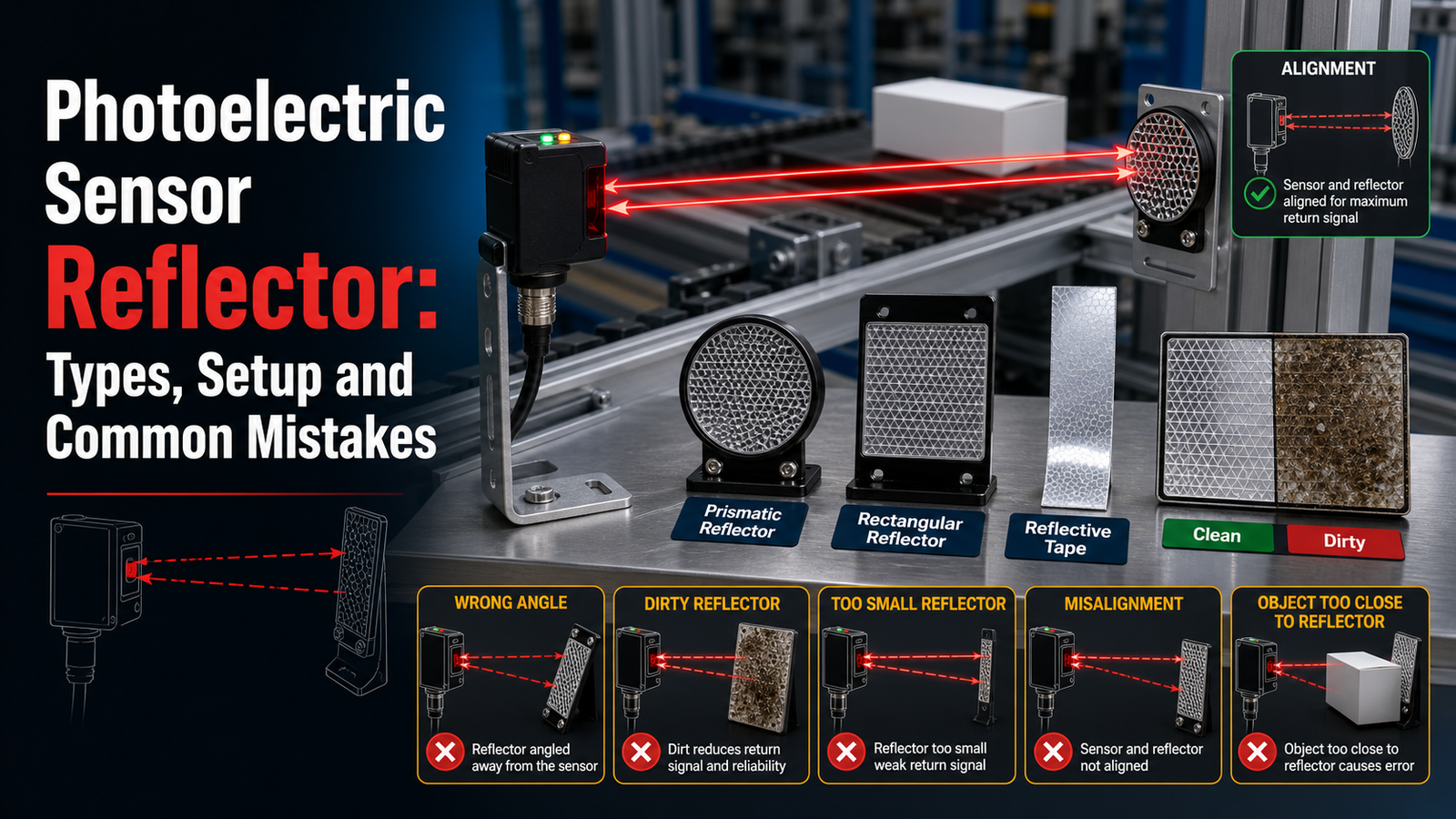
A photoelectric sensor reflector is a targeted mirror or prism that bounces a sensor’s light beam back to its receiver, letting the sensor detect when an object breaks that beam. Corner-cube prism versions return light within a 3° angle and support detection ranges up to 10 meters using a single reflector. Choosing the wrong reflector drives false triggers, and misalignment over 2° accounts for roughly half of production-line “sensor faults.” The global market is projected to grow from US$148 million in 2025 to USapproximately $237[1] million by 2032.
This guide sets out to answer the questions engineers are genuinely searching for. What types of reflectors are out there, and when should you reach for each one? How do you align and mount one the right way? Why do corner-cube prisms tend to outperform flat mirrors? And which setup mistakes end up causing the most periods when the line wasn’t running?
Quick Takeaways
- Corner-cube prisms return light within 3°, outperforming flat mirrors reliably.
- Retroreflective sensors detect objects up to 10 meters with one reflector.
- Use polarized reflectors to block false triggers from shiny surfaces.
- Keep misalignment under 2° to prevent intermittent sensor faults.
- Match reflector size to beam spread; undersized tape cuts range approximately 30%.
What Does a Photoelectric Sensor Reflector Actually Do?
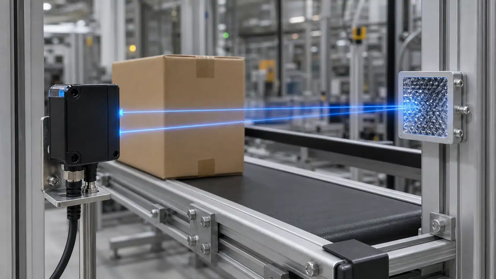
A photoelectric sensor reflector bounces the sensor’s emitted light beam straight back to its built-in receiver, so the sensor picks up an object the very moment that object breaks the beam. This design lets one housing hold both the light source and the receiver, so you wire and power a single unit instead of two separate pieces. When a target passes between the sensor and the reflector, it interrupts the returning light and the receiver output switches over. Because the reflector, and not the object itself, supplies the return signal, detection stays mostly independent of the target’s own color or how shiny it happens to be.
So why not just use a second sensor facing the first one? You actually could, but that turns into a different mode called through-beam, which needs two devices, two power feeds, and two alignment points. A reflector, on the other hand, is a passive part with no wiring at all. That simplicity is basically why retroreflective sensors are expected to hold 50.60% of the photoelectric sensor market in 2026, and lower cost compared to the other modes is what keeps pushing that number.
The reflector also sends back a strong, well-defined beam, which gives retroreflective setups a longer working range than diffuse sensors that lean on the weak scatter coming off the target surface. One practical thing follows from all of this. You really want to match the reflector to your sensor’s beam wavelength, since a mismatched reflector can drop the return signal enough to cause missed detections.
Which Photoelectric Sensing Modes Use Reflectors and Which Don’t?
Only retroreflective and polarized retroreflective modes need a photoelectric sensor reflector. Through-beam and diffuse modes don’t. Retroreflective sensors are expected to hold 50.60% of the global photoelectric sensor market in 2026, largely because pairing one sensor with a passive reflector costs less than wiring two separate units.
The three modes split by where the light travels and what returns it.
- Through-beam: A separate emitter and receiver face each other. The target breaks the beam. No reflector — instead you wire and power two housings, which raises install labor.
- Retroreflective: Emitter and receiver sit in one housing. A reflector bounces the beam back, and detection stays largely independent of the target’s own color or shine.
- Diffuse: Light bounces off the target itself back to the sensor. No reflector needed. This segment is projected to grow at an 8.9% CAGR through 2032, partly because skipping the reflector cuts setup steps.
Reflectors earn their place at long ranges up to 10 meters, where diffuse sensing gets unreliable. Their weakness is the near field: a standard reflector mounted too close creates a dead zone within roughly 100mm of the sensor. Fix this with a coaxial polarized reflective setup, which detects tiny light changes and mounts flush against the sensor with no dead zone.
Pick the mode before you buy. Detecting a clear film? Go polarized retroreflective. Tight space with no room for a target on both sides? Diffuse wins.
Why Does a Reflector Cut Your Sensor’s Effective Range?
A photoelectric sensor reflector cuts down on range because it only sends back part of the light that the emitter throws out in the first place. A sensor that is rated for 4 m when used in through-beam mode will often reach only 60 to approximately 80%[3] of its retroreflective rating once you pair it with a small reflector. The smaller the reflector, the less light comes bouncing back, so you really have to reduce your expected maximum distance for every actual installation you do.
This drop in performance is called optical return loss, which simply means light gets lost on the way back. The beam that leaves the emitter spreads out wider as it travels farther. A tiny reflector only catches a slim portion of that cone of light, and then it sends an even smaller portion back toward the receiver. Retroreflective sensors already work better than diffuse mode does, because the reflector returns a strong and clearly shaped beam (Pepperl+Fuchs, 2024), though that head start disappears quickly when the target is too small for the job.
How Does Reflector Size Change the Range Multiplier?
The size of the reflector sets a range multiplier that works against the maximum listed on the datasheet. Larger reflectors keep more of the rated distance intact. You can use the following as a guide for how much to reduce your figures:
| Reflector diameter/size | Effective range multiplier |
|---|---|
| 80 mm round (full-size) | 1.0× |
| 50 mm[4] round | 0.85× |
| 25 mm round | 0.6× |
| Reflective tape 25×25 mm[5] | 0.3× |
Here is a useful rule to follow. Choose a reflector that keeps your working distance below 70% of the rated maximum. That extra margin gives you room to absorb dust that builds up over time, slight misalignment of the parts, and the natural aging of the lens. Those three factors are essentially what push a borderline setup into giving you false trips within just a few weeks.
Corner-Cube, Reflective Tape, or Micro-Prism Film — Which Reflector Fits Your Sensor?
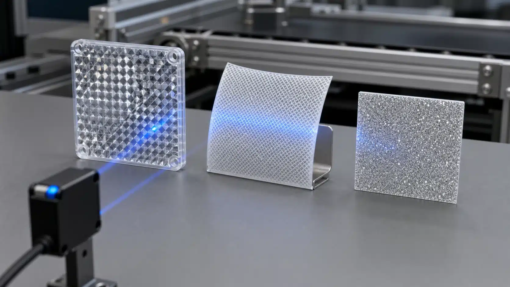
Go with a corner-cube prismatic reflector when you have polarized sensors, use reflective tape only for the basic non-polarized ones, and pick micro-prism film for situations where space is really tight. The decision comes down to one thing, which is whether or not your sensor is polarized. Retroreflective sensors, the kind that actually need a reflector, are expected to hold 50.60%[6] of the global market in 2026 because they cost so little, according to Fortune Business Insights, so matching the reflector correctly really does matter.
Why does reflective tape fail with polarized sensors?
Reflective tape scatters the light without keeping its polarization angle intact. A polarized sensor sends out light through a filter that only accepts light rotated 90 degrees when it comes back. A corner-cube prism twists the beam the right way, but tape simply doesn’t do that. If you put tape on a polarized sensor, it reads the tape’s glare as a “clear” signal, and the beam never actually breaks. That is depolarization failure, and it tricks the sensor into missing its targets entirely.
How do the three reflector types compare?
| Reflector | Material | Return efficiency | Polarized-safe? | Relative cost |
|---|---|---|---|---|
| Corner-cube prism | Molded acrylic prisms | ~80% | Yes | High |
| Micro-prism film | Thin adhesive prism sheet | ~50%[7] | Yes | Medium |
| Reflective tape | Glass-bead coating | ~30% | No | Low |
Micro-prism film really shines in the cramped spots, things like conveyors, robot arms, and curved surfaces, where a rigid corner-cube just won’t fit. It gives up a bit of range in exchange for that flexibility. And you should generally save the tape for short-range, non-polarized jobs where the budget matters more than performance does. For any polarized setup, the photoelectric sensor reflector you choose still has to preserve that polarization angle, so the corner-cube or the micro-prism film remains the safe pick.
How Do You Detect Shiny or Reflective Targets Without False Triggers?
Use a polarized retroreflective photoelectric sensor paired with a corner-cube reflector. Polarizing filters make the sensor ignore direct glare from chrome, foil, or glossy film, and only accept the twisted light returning from the corner-cube reflector. Because detection stays largely independent of the target’s own reflectivity, a shiny can no longer fake the reflector’s signal.
⚠️ Common mistake: Using a flat mirror or undersized reflective tape instead of a corner-cube prism. This happens because engineers treat any shiny surface as equivalent, but flat mirrors demand near-perfect alignment and undersized tape cuts detection range by 30%[8]. The fix: use a properly sized corner-cube prism that returns light within 3° and keep misalignment under 2°.
Why Does a Standard Sensor Get Fooled by Shiny Objects?
A basic retroreflective sensor treats any strong bounce-back as “beam intact.” A mirror-like target, a chrome bottle cap or an aluminum tray, reflects light almost as brightly as the reflector itself. The receiver reads that glare, thinks the beam is clear, and misses the part. On a fast bottling line running 600 units per minute, that means dozens of skipped detections before anyone notices.
How Do Polarized Sensors Block the False Signal?
Polarized models add two filters set 90 degrees apart. The emitter sends light in one plane; a corner-cube reflector rotates that plane so the receiver’s filter accepts it. A flat shiny surface reflects light in the same plane it received, so the crossed filter blocks it. Random glare gets rejected while the true reflector signal passes.
When Should You Switch to Through-Beam Instead?
Drop the reflector setup when targets are highly polished, mirror-flat, and moving fast, cases where even a polarized filter can be overwhelmed. A through-beam pair puts emitter and receiver on opposite sides, so no reflection logic is involved at all. Short of that, tilt the reflector 10,15 degrees off perpendicular on stubborn glossy jobs, this angle dumps stray glare away from the receiver while keeping the corner-cube return strong.
How Do You Mount and Align a Reflector Step by Step?
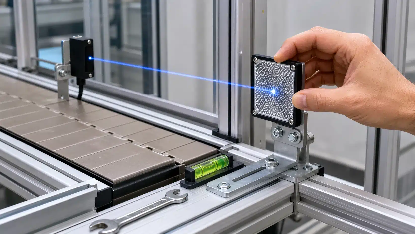
Mount the photoelectric sensor reflector directly opposite the sensor, roughly perpendicular, then fine-tune using the sensor’s alignment LED and margin indicator until the received signal peaks. A proper setup takes under five minutes, and because retroreflective sensors are set to make up about 50.6% of the global market in 2026 for their affordability, this alignment routine repeats across most sensor installs.
What Order Should You Follow?
Work through these steps in sequence:
- Rough-aim with the LED: Power the sensor, watch its alignment LED, and tilt the reflector until the light turns on. This gets you into the detection zone.
- Read the margin indicator: Most sensors show excess gain (received light versus the minimum needed). Aim for a margin of at least 3x, so dust and drift won’t cause false trips.
- Lock at peak signal: Nudge the reflector left, right, up, down. Find where the margin reading is highest, then tighten the mount hard.
- Verify with a target pass: Move a real object through the beam five to ten times. Every pass should switch the output cleanly.
How Precise Does Alignment Need to Be?
Keep the reflector within about 5 degrees of perpendicular for corner-cube prisms, which tolerate more angle error than flat tape. Respect the sensor’s minimum standoff distance too, mounting a reflector closer than spec can push the target into a blind zone. For vertical installs, set a bubble level against the reflector face before locking bolts. A tilt of just 2 to 3 degrees on tall conveyor guards can drop your margin below the safe threshold, so verify the level twice.
How Do You Keep Reflectors Working in Dusty or Vibration-Prone Environments?
Match the fix to the hazard: use anti-static or self-cleaning reflectors for dust, IP67-rated housings for washdown lines, and thread-locked, vibration-damped brackets on conveyors. Dust, steam, and smoke degrade reflector performance and drive up system cost and complexity in long-range setups, per 2024 market research. Clean before excess gain drops too low.
What Fixes Which Environmental Hazard?
Each threat has a specific countermeasure. Guessing wastes downtime.
| Hazard | Fix | Key spec |
|---|---|---|
| Airborne dust | Anti-static reflector face | Surface resistivity below 10⁹ Ω |
| Washdown / steam | Sealed housing | IP67 or IP69K |
| Conveyor vibration | Thread-lock + damped bracket | Loctite 243, rubber isolator |
| Oil mist buildup | Self-cleaning coating | Hydrophobic film |
Excess gain is the extra light margin above the minimum needed to trigger. Anti-static faces repel charged dust particles, cutting buildup on the photoelectric sensor reflector by holding a neutral surface charge.
How Often Should You Clean the Reflector?
Tie cleaning to excess-gain readings, not the calendar. Wipe the reflector when the sensor’s excess gain margin falls below 1.5× the trigger threshold. On a heavy-dust conveyor, that often means weekly; in a clean room, quarterly is enough. Set an alarm output that flags marginal gain early, so it warns you before a false clear signal shuts down the line.
Seven Reflector Errors That Cause Detection Faults and How to Fix Them
Most reflector faults trace back to seven mistakes, and each has a single clear fix. Since retroreflective sensors are set to hold 50.60% of the photoelectric sensor market in 2026, these errors show up on countless production lines. Match your symptom to the root cause below, and you can usually restore stable detection in under five minutes.
| Symptom | Root Cause | Fix |
|---|---|---|
| Beam won’t lock even at close range | Flat tape used with a polarized sensor | Swap in a corner-cube prismatic reflector |
| Output drops in and out | Distance exceeds reflector rating | Move reflector closer or use a larger-gain type |
| Weak signal margin (under 2x) | Slight misalignment off the beam center | Re-aim until margin reads 3x or higher |
| Gradual sensitivity loss over weeks | Dust film on the reflector face | Wipe with a dry lint-free cloth |
| False triggers on shiny cans or foil | Wrong tilt reflecting off the target itself | Tilt sensor 10–15° and use polarized mode |
| Range shorter than spec | Reflector smaller than the beam spot | Fit a reflector at least as wide as the spot |
| Polarized sensor sees ghost objects | Depolarizing tape or wrap on the reflector | Remove tape; keep the prism face bare |
One field tip: always check the excess gain reading, not just the on/off state. A link that works at 1.5x margin today will fail after a week of dust. Target a photoelectric sensor reflector setup that reads 3x or more.
Frequently Asked Questions About Photoelectric Sensor Reflectors
No, you can’t use any reflector with any sensor. A polarized retroreflective sensor needs a corner-cube prismatic reflector to work at all, while reflective tape only suits basic non-polarized models. Matching the two correctly is the single biggest factor in reliable detection.
Can you use any reflector with any sensor?
No. Polarized sensors emit light through a filter and only accept light whose polarization has been rotated 90 degrees. Only a corner-cube prism does that rotation. Feed a polarized sensor reflective tape and it may never switch. Standard non-polarized retroreflective sensors are more forgiving and will read tape or film.
How far can a photoelectric sensor reflector work?
Range depends on the reflector’s return efficiency, not the reflector alone. A corner-cube prism at full size can support ranges up to 10 meters or more on many industrial sensors, while a small tape patch may cap out under 1 meter. Retroreflective mode still beats diffuse mode because the reflector returns a strong, well-defined beam, as Pepperl+Fuchs engineering notes confirm.
Do polarized sensors need special reflectors?
Yes. Coaxial polarized retroreflective sensors need reflectors that rotate the light polarization, and they detect very small light changes. This lets you mount the reflector close to the sensor with no dead zone.
Can reflective tape replace a prismatic reflector?
Only for short-range, non-polarized setups. Tape scatters light and returns roughly 30%[9] versus a prism’s ~80%, so range and stability drop. With over 190 standardized reflector products listed online in 2026, buying the matched prism is usually cheaper than troubleshooting tape faults.
Choosing and Setting Up the Right Reflector — Key Takeaways
Match the reflector to your sensor mode first, derate the range for real conditions, then lock the alignment against vibration and dirt. Retroreflective sensors, which need a reflector opposite the sensor, are expected to hold 50.60% of the photoelectric sensor market in 2026, so getting the reflector choice right matters for most installs.
Three rules cover the pairing. Polarized sensors need a corner-cube prismatic reflector. Standard retroreflective sensors work with reflective tape or micro-prism film. And whenever your target is shiny metal, glass, or wrapped in film, only a polarized sensor plus corner-cube combo blocks false triggers.
Then account for loss. Cut the rated range by 30,50% for dust, condensation, or a smaller-than-spec reflector. Buying a reflector at 60%[10] of your maximum distance gives you working headroom for the light beam.
Run this checklist before you power up:
- Mode match: polarized sensor → corner-cube; non-polarized → tape or film.
- Size and range: reflector spans no more than 60% of rated distance.
- Alignment: reflector perpendicular to sensor, LED excess-gain indicator at maximum.
- Environment fix: anti-static or sealed reflector for dust; thread-lock mount for vibration.
- Margin check: verify stable switching at your dirtiest, foggiest state — not a clean bench.
Spec the photoelectric sensor reflector against your worst-case detection scenario, never your best. A setup that reads clean in a dry test cell can drop out the first time steam or dust coats the prism face.




