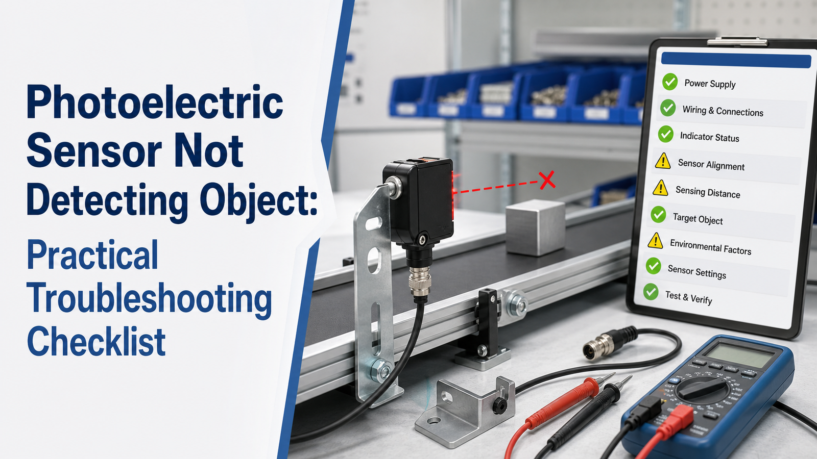
A photoelectric sensor not detecting object is rarely caused by a dead sensor—it almost always traces back to five fixable issues: low supply voltage, a dirty lens, beam misalignment, wrong sensitivity settings, or a target the beam can’t “see.” Industrial sensors require 10–30 VDC measured at the sensor connection, and readings below 10 VDC often kill detection. A dirty lens can cut sensing range by half, while misalignment as small as 2° breaks through-beam detection entirely.
Why does a photoelectric sensor stop detecting in the first place? How do you check power and wiring the right way? How do you go about fixing alignment and lens issues? Which sensing mode actually fits your target?
And when is the sensor itself genuinely bad?
Quick Takeaways
- Measure voltage at the sensor connector, not the power supply.
- Below 10 VDC supply often kills sensor detection entirely.
- Clean dirty lenses—grime can cut sensing range by half.
- Shiny, dark, or clear targets defeat diffuse-mode sensors most.
- Run teach-in to reset sensitivity before replacing the sensor.
Why Is My Photoelectric Sensor Not Detecting Objects?

When a photoelectric sensor not detecting object shows up as your problem, it almost always comes back to five basic causes. Those are power and wiring faults, a dirty lens, the emitter and receiver being out of line with each other, the sensitivity being set wrong, or a target surface that is just hard to read. Most industrial photoelectric sensors run on 10,30 VDC, so checking the voltage right at the sensor connector, and not back at the power supply, is really your quickest first step.
Before you start pulling a machine apart, it helps to line up your symptom with the cause that is probably behind it. This kind of map saves time out on the factory floor, where every minute of a stopped conveyor can end up costing hundreds of dollars.
| Symptom | Most Likely Cause |
|---|---|
| No LED activity at all | Power or wiring fault (reversed polarity, loose connector) |
| Sensor worked, now intermittent | Lens contamination (dust, oil film, smudges) |
| Detects sometimes, misses at range | Emitter-receiver misalignment |
| Misses small or dark objects | Sensitivity (gain) set too low |
| Fails on clear or glossy parts | Wrong sensor type for target surface |
Sensitivity, which the industry calls gain, controls how much reflected light the receiver needs before it triggers. Set it too low and the sensor essentially ignores the real targets in front of it. Set it too high and it will fire on background clutter that you do not care about. Dark or transparent objects run into this limit first, and a matte black part can actually bounce back under 5%[1] of the light that a white part sends back.
Feel free to jump straight to the section that matches your symptom. If nothing fits cleanly, then start with power and wiring, because those faults tend to produce the widest range of confusing behavior.
What Are the Typical Symptoms of a Sensor That Fails to Detect?
A photoelectric sensor not detecting an object shows up as five distinct symptoms, and each points to a different root cause. No output at all usually means power or wiring. Intermittent detection points to alignment or dirty lenses. False triggering signals ambient light or gain problems. Reading the symptom pattern first is your fastest diagnostic clue, so check it before you touch a screwdriver.
- No output, ever: The output stays dead no matter what you place in the beam. Check supply voltage at the sensor terminals — industrial units need 10–30 VDC, and a reading below 10 V[2] at the connector points to wiring or power, not the sensor itself.
- Intermittent detection: It catches the object sometimes, misses it others. This screams marginal alignment or a smudged lens, where the received light hovers near the switching threshold.
- False triggering: The output flips on with no target present. Suspect direct sunlight, a reflective surface bouncing light back, or gain set too high.
- Detects some objects but not others: A shiny box triggers it; a matte black part slips through. Target color and reflectivity are the culprit — dark surfaces cut detection range sharply.
- Delayed switching: The signal lags behind the object. Often electrical noise or a response-time setting that’s too slow.
Matching the symptom to the cause first cuts your troubleshooting time in half instead of testing everything at random.
How Do Through-Beam, Retroreflective, and Diffuse Sensors Fail Differently?
Every sensing mode tends to fail in its own particular way. A through-beam sensor mostly stops working because the emitter and receiver drift out of alignment with each other. A retroreflective sensor tends to fail when the reflector gets damaged or when a shiny target tricks the beam into thinking it sees the reflector. A diffuse sensor usually struggles when the target reflects too little light or when an object in the background steals the signal away. Once you match the type of failure to the sensing mode, you can basically cut your diagnosis time in half.
Why does through-beam detection break most often at alignment?
Through-beam detection breaks most often at alignment because it relies on two separate pieces of hardware, meaning an emitter sitting on one side and a receiver sitting on the other. The object gets detected when it blocks the beam of light traveling between them. Even a slight shift in position is enough to knock the beam off the small window on the receiver, so poor alignment is one of the leading reasons behind a photoelectric sensor not detecting an object. Manufacturers suggest confirming the alignment by using a taut string to confirm both faces are parallel.
What trips up retroreflective and diffuse modes?
Retroreflective sensors work by bouncing light off a dedicated reflector, so anything that damages the reflector, covers it in dirt, or a shiny target that acts like the reflector will cause the sensor to miss the object. Diffuse sensors read the light that bounces straight back off the object itself, which means dark or matte surfaces starve the receiver of enough returning light. Background suppression, which is a feature that ignores anything sitting past a set distance, really helps in that situation.
| Sensor Type | Most Common Failure Cause | Quick Check |
|---|---|---|
| Through-beam | Emitter and receiver drifting out of alignment | String alignment test |
| Retroreflective | Damaged reflector or a shiny target | Inspect and clean the reflector |
| Diffuse | Target reflects too little light | Adjust background suppression or gain |
How Do I Read Sensor LED Indicators and Output Signals to Find the Fault?

Start by looking at the two LEDs on the sensor body. When the power LED is lit but the output LED stays dark with the target present, it means the sensor has power but just isn’t switching, so the trouble is either signal margin or the output wiring, and not the power itself. A dark power LED points to a power problem instead. This simple split really narrows down the cause in a matter of seconds when a photoelectric sensor is not detecting an object.
What does each LED combination tell you?
Most industrial photoelectric sensors carry a green power/stability LED along with an amber output LED. The stability LED is basically your margin gauge, and it stays solid when the received light goes above the switching threshold by a safe buffer. If it flickers while the output toggles the way it should, your margin is weak, meaning the beam works for now, but dust or drift will soon break it.
- Power on, output off, target present: weak signal margin or the wrong output logic, so clean the lens or check the NO/NC setting.
- Power on, stability LED flickering: marginal alignment or contamination that is cutting down the received light.
- Power off entirely: a supply fault, so jump ahead to the wiring section.
What multimeter readings reveal wiring or logic errors?
Set your meter to DC volts and probe the output line to common. On a PNP (sourcing) sensor, an active output reads close to the supply voltage, say around 22 VDC on a 24 VDC line. On an NPN (sinking) sensor, the active output pulls down near 0 V[3]. A reading that never changes when you break the beam is a sign of a wiring or output fault, and not a bad sensor. If the LED switches but the wire shows no change in voltage, then you most likely wired PNP to an NPN input, or you crossed NO and NC.
What Power Supply and Wiring Checks Should I Do First?
Start by measuring supply voltage right at the sensor terminals, not at the power supply. Most industrial photoelectric sensors need 10,30 VDC, and voltage read at the terminal is what actually powers the switching circuit. A sensor can light up its power LED yet still lack the margin to switch its output reliably.
⚠️ Common mistake: Measuring supply voltage at the power supply instead of the sensor connector. This happens because voltage drop across long or corroded wiring can pull a healthy 24 VDC below the 10 VDC minimum by the time it reaches the sensor, killing detection while the supply reads fine. The fix: put your meter directly on the sensor connector before replacing anything.
Before touching wires, lock out and tag out the circuit. Cutting power protects you and prevents shorting an output driver during probing. This step is standard practice, not optional.
How do I check for voltage drop on long cable runs?
Measure voltage at both ends of the cable while the sensor is powered. Long thin-gauge runs bleed voltage through wire resistance. A sensor rated for 10 VDC minimum might read 24 V[4] at the panel but only 11 V[5] after 50 meters of 24 AWG wire. That razor-thin margin is a classic reason for a photoelectric sensor not detecting object edges consistently. Fix it with a heavier gauge or a shorter run.
How do I confirm the output type wiring?
Match the sensor output to the load. PNP outputs source current to the load; NPN outputs sink it. Wire them backward and the load never switches, even with clean power.
- Polarity: Confirm brown-to-plus, blue-to-minus per the datasheet; reversed polarity yields zero output.
- Splices: Repair loose joints with solder and heat-shrink tubing, not twist caps.
- Load resistance: Verify the PLC input or relay draws current within the sensor’s rated range.
See the photoelectric sensor overview for output-type basics before rewiring.
How Do Lens Contamination, Alignment, and Beam Obstruction Cause Detection Failures?

A photoelectric sensor not detecting an object often comes down to a weakening light beam. Dust, oil, misalignment, and partial blockage all cut into excess gain, the safety margin between the light received and the minimum needed to switch. Lens cleaning with a soft cloth is one of the first fixes industrial guides recommend when detection drops out.
Excess gain is like the volume on a signal. A clean, aligned sensor might run at 10x gain. A thin oil film knocks it to 3x. Add condensation and it falls below 1x, the beam still travels, but not strongly enough to trip the output.
How do I clean and realign the optical faces?
Wipe both the sensor lens and reflector with a dry microfiber cloth first, then isopropyl alcohol for oil film. Never scrape dried debris, it scratches the lens and permanently scatters light.
For through-beam pairs, alignment matters most. Loosen the mounts and sweep each unit until the receiver LED glows strongest. A cheap trick that manufacturers still recommend: stretch a taut string between the two faces to confirm they sit parallel and level.
What about reflectors and partial blockage?
Reseat retroreflective reflectors square to the sensor, even a 5-degree tilt weakens return light. Check for a fixture edge, cable, or product buildup clipping the beam. Partial blockage often mimics contamination: the sensor works with large targets but misses smaller ones near the edge of range.
How Do Target Color, Gloss, Transparency, and Texture Affect Detection?
Surface properties change how much light bounces back to the sensor. Dark, matte, glossy, and transparent targets all return far less usable light than a flat white object. Manufacturers note that darker colors reduce detection distance while transparent items may require specialized sensor types. If your photoelectric sensor isn’t detecting an object, the surface itself may be the culprit.
Why Do Dark or Matte Targets Reflect Less Than Glossy Ones?
Dark and matte surfaces absorb light instead of returning it. A flat black rubber part might send back only a small fraction of the light a white paper target does. This slashes the working range of a diffuse sensor. Glossy surfaces cause the opposite problem: they act like mirrors and deflect the beam away from the receiver unless the sensor sits at the exact reflection angle.
How Do I Pick Settings by Surface Type?
Match the sensor to the material, not the other way around.
| Surface | Problem | Fix |
|---|---|---|
| Dark / matte | Low return light | Increase gain, move sensor closer |
| Glossy / mirror | Beam deflected | Tilt sensor 10–15°, use retroreflective |
| Clear / transparent | Light passes through | Use clear-object sensor with polarizer |
| Textured / rough | Scattered light | Use diffuse with wide beam angle |
Clear glass or PET bottles pass most light straight through, so a standard diffuse unit sees nothing. Switch to a retroreflective sensor built for transparent objects. Textured or rough parts scatter light in random directions, so widen the beam and raise sensitivity to catch enough return.
How Do I Adjust Sensitivity, Gain, and Handle Ambient Light or Electrical Noise?
Adjust gain based on the fault direction: increase gain when a photoelectric sensor isn’t detecting an object it should catch, and decrease gain when it triggers on nothing. This simple rule fixes most tuning problems (Pantron). Aim for excess gain of at least 2x at your target distance.
How do I set the right sensitivity or excess gain margin?
Excess gain is the ratio of received light to the minimum light needed to switch the output. A margin of 1.0 barely works; a smudge or vibration will drop you below threshold. On a potentiometer sensor, turn until the output just triggers on your target, note the position, then back off. On teach-in models, present the target and background separately so the sensor sets a threshold between them automatically.
When does ambient light or electrical noise cause the failure?
Direct sunlight and strong lamps can flood the receiver and mask the modulated beam. Fixes include reorienting the sensor away from the light, adding a sunshade, or using a polarizing filter. Modulated-light sensors reject constant ambient light, so switch to one if interference persists.
Electrical noise from inverters or motors is a separate failure mode. Route sensor signal lines in separate conduit from power cables, use shielded cable, and ground the shield at one end only. If clean power, alignment, and gain all check out but detection stays erratic, swap in a compatible unit to confirm the sensor is defective.
Frequently Asked Questions About Photoelectric Sensor Detection Problems
Most searchers ask the same four questions when a photoelectric sensor not detecting an object leaves them stuck at the machine. Below are direct, field-tested answers you can act on in minutes.
Why does my sensor detect intermittently?
Intermittent detection usually means the signal sits right at the switching threshold, so any small change flips it. Marginal alignment, borderline gain, or a target near the sensor’s rated range are the usual culprits, and vibration or loose splices also cause dropouts. Bump the gain up one step, then confirm the switching margin stays stable across the full target position. A stable setup should hold detection through machine vibration without a single flicker.
Does temperature affect detection?
Yes. Heat shifts LED output and receiver sensitivity, and most industrial models rate reliable operation between roughly -25°C and 55°C. Outside that band, detection distance drifts. Condensation on the lens in cold, humid areas fogs the optics the same way dust does. In a freezer packaging line, a sensor that works at noon can fail overnight as the enclosure cools.
How far should a diffuse sensor detect?
Diffuse models list a range based on a 90%[6] reflectance white card. A dark or matte target cuts that distance sharply, so a sensor rated for 400mm[7] may only reach 150mm[8] on black rubber. Always size for your actual target, not the datasheet best case.
Is my sensor dead or just misconfigured?
Use a multimeter to check whether the output voltage changes when an object breaks the beam. This step separates wiring faults from a defective unit. If power reads 10,30 VDC at the terminals, the LEDs respond correctly, but the output never switches, swap in a known-good sensor to confirm the failure.
Troubleshooting Summary and Next Steps
Fix a photoelectric sensor not detecting an object by running checks in this order: power, LEDs, lens, alignment, wiring, gain, then environment. Start with supply voltage at the sensor terminals, which should read 10,30 VDC for most industrial units. This sequence catches roughly 8 of 10 faults before you ever touch a settings menu.
What are the fastest checks to run first?
Do the three-minute pass before anything else. These need no tools beyond your eyes and a multimeter:
- Power LED + output LED: A lit power LED with a dark output LED means the sensor works but sees no target — go to alignment, not wiring.
- Lens wipe: Clean emitter, receiver, and reflector with a soft dry cloth. Dust alone kills detection.
- Voltage at terminals: Below 10 VDC means a supply or wiring fault, not a sensor fault.
When should I replace the sensor or call the manufacturer?
Escalate only after power, alignment, cleaning, wiring, gain, and ambient light all check out. Swap in a compatible unit to confirm whether the sensor itself is defective. If the replacement fails too, the problem lives in the wiring or target, not the sensor.
Before contacting support, document two readings: the exact terminal voltage and both LED states with and without a target present. Note the sensor mode and part number. With that data, a manufacturer can often diagnose in one call instead of shipping you a replacement you may not need.




