
Sensors for Robotic Arms: Position, Gripper, Vision, Force and Safety
A robotic arm needs different feedback for different decisions: joint position for motion, part sensing for pickup and release, vision for changing part poses, and force feedback for contact. Choose around the fact the next action requires—and keep personnel protection in a documented safety architecture.
Which sensors does a robotic arm actually need?
Start with the fact that changes the next robot action. Joint feedback tells the controller how the arm is positioned. A tooling sensor checks a part or mechanism. Vision locates features, force feedback measures contact, and safety functions address hazardous motion. These are different jobs—not interchangeable levels of sensor quality.
For a fixed pick-and-place station, simple presence and tooling checks may be sufficient. Randomly arranged parts add a localization problem; insertion or surface finishing adds a contact-control problem. First ask the robot supplier which feedback is already installed and accessible. Do not replace or modify internal joint feedback as if it were an ordinary external switch.
| Required information | Starting point | What remains unproved |
|---|---|---|
| Joint position and motion | The robot's documented encoder or resolver feedback | Whether the correct part is held or the tool is aligned with the real fixture |
| Part or tooling state | Inductive, photoelectric, fiber, cylinder-position or vacuum sensing, as appropriate | Part identity, full pose or secure retention unless the method specifically checks them |
| Position and orientation of a part | 2D or 3D vision with robot-coordinate calibration | Whether the subsequent grip or placement succeeded |
| Contact load | Supported robot force feedback or a suitable force/torque sensor | Correct assembly, or personnel safety, from a load value alone |
| A safety-related condition | Documented safety devices and control functions selected through risk assessment | Complete application safety from any one component's rating |
Why joint feedback is not independent tool-position measurement
An encoder measures rotation; the controller uses joint information and a kinematic model to calculate the tool center point (TCP), the reference point used to program tool motion. A changed gripper finger, shifted fixture or incorrect TCP offset can therefore cause a missed pick even when the joint feedback is working. A smaller encoder increment does not, by itself, prove better accuracy at the workpiece.
How can the gripper confirm that it really holds the part?
Check the physical condition you need, not just the command you sent. “Close requested,” “jaws reached position” and “correct part retained” are three different observations. Existing gripper feedback may answer the question, but its documented object-detection logic and limitations must match the job.
Separate actuator position from part presence
A magnetic cylinder switch can confirm that a compatible magnet-equipped piston has reached its sensing point. An inductive switch can detect a metal jaw or fixture flag. Neither directly proves that a workpiece is between the fingers. Where an empty grip can pass the actuator check, add or use a measurement of the workpiece itself.
For a vacuum tool, vacuum feedback indicates the pressure condition at its measurement point. Decide whether that observation distinguishes the intended pick from leakage, a blocked line or an incorrect object. Do not equate a vacuum threshold with proof of part identity or unrestricted lifting capacity.
Choose a usable sensing path inside the tooling
Metal at a short, controlled gap: consider inductive sensing. Check the actual metal, target dimensions and mounting clearance; the surrounding metal fingers must not become the detected target.
An accessible optical path: compare photoelectric modes. Through-beam sensing needs opposed mounting positions; one-sided diffuse sensing relies on returned light and must distinguish the part from the background. A compact fiber head can help in narrow fingers, but it still needs a workable beam path and protected fiber routing.
No useful optical path: capacitive sensing may be worth evaluating for a suitable material. Include nearby tooling, moisture and residue in the trial rather than assuming that every non-metal part produces the same response.
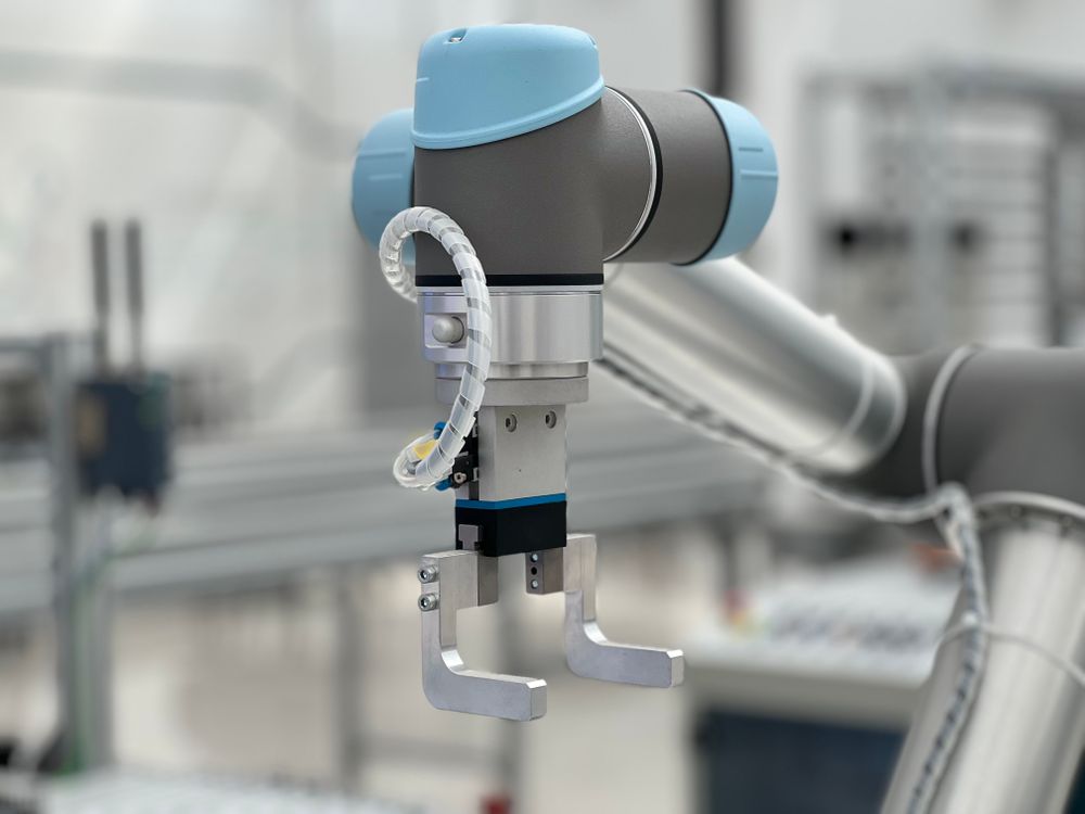
Also prove that the part has left the gripper
A successful pickup is only half the sequence. After release, a component can remain caught in the fingers. If the program treats “open commanded” as “gripper empty,” the next motion can carry an unexpected object into the station.
Documented manufacturer example. SensoPart describes a double-gripper application handling dark, shiny parts. It distinguishes correct part position during gripping from complete clearance after release. Its proposed FT 10-BH solution uses two switching points for those different checks. This is a SensoPart application example—not an xsz sensor installation or a universal capability of diffuse sensors. Read the original application.
The transferable lesson is to specify both the captured state and the released state. One threshold may not separate all the positions that matter.
When should you use vision instead of a point sensor?
Use vision when a yes/no checkpoint cannot supply the location, orientation, identity or inspection result the task needs. A point sensor is often sufficient for a repeatable fixture. Vision becomes more useful when the robot must adapt its pick pose to changing part presentation.
Choose 2D or 3D around the missing coordinate
A controlled work plane is a good starting condition for 2D guidance: the unknowns may be position on that plane and rotation within it. Variable heights, stacked parts or three-dimensional orientation can require depth information and a suitable 3D method. A higher-resolution image cannot recover a feature hidden behind another part; test visibility, lighting and the worst surface finish before choosing a camera.
For a moving conveyor, the location must also correspond to the right moment. Account for acquisition, processing, communication and target movement before the robot uses the result. Conveyor tracking, when required, needs a supported position relationship—not simply a fast camera.
If the camera finds the part but the robot misses it
Do not immediately replace the camera. Check the image result first, then how that result is transformed into the robot's coordinate system, and finally the active TCP and pickup offset. A fixed camera and a camera carried by the robot have different geometric relationships; changing a mount can invalidate the relationship used by the program.
Illustrative diagnosis: a stationary part is found consistently in saved images, but commanded picks have a repeatable offset after a tooling change. This makes the active TCP, tool offset and calibration worth checking before optical sensitivity. It is a diagnostic direction, not proof of the cause. If the offset appears only while the conveyor moves, also examine result timing and tracking.
Cognex's In-Sight 2D Robot Guidance documentation illustrates the principle by mapping robot TCP coordinates to image coordinates and saving a calibration file. The exact calibration routine belongs to the installed system; it is not a universal sequence for all vision-guided robots.
When is force feedback useful, and is the robot's built-in sensing enough?
Force feedback is useful when contact should change the motion—for example, when searching for an insertion opening or maintaining pressure against a surface. Before adding hardware, identify whether the robot provides a measured wrist force, joint torque information or a model-derived estimate. Check the documented accuracy, update behavior, coordinate frame and supported control functions against the process.
An external multi-axis force/torque sensor can provide measurements close to the tool when the existing feedback does not meet the requirement. Selection must cover both the small change you need to distinguish and the largest forces and moments the tooling can impose. A force reading also needs compatible control software; fitting a transducer does not automatically create force-controlled motion.
Why tool length matters as much as force range
Illustrative calculation. Assume a 30 N lateral force acts perpendicular to a tool, 0.20 m from the force/torque sensor origin. The moment contribution is 30 N × 0.20 m = 6 N·m. At 0.40 m, the same force produces 12 N·m.
A sensor that covers 30 N can still have insufficient moment capacity. These figures describe only the assumed force and lever arm; include tool weight, acceleration, other load components and the manufacturer's combined-load and overload limits before selecting a model.
Do not zero away the contact you are trying to measure
Define the reference condition, payload and gravity compensation before interpreting a load. A zero operation establishes a baseline; it is not a repair for an incorrect setup. For example, Universal Robots' SW10.8 set_target_payload documentation says that updating the payload also resets the internal force/torque measurement, and acceleration during that reset affects the reading. Follow the installed robot's instructions rather than copying a zeroing command into every cycle.
For assembly, combine the relevant contact result with completion evidence such as final position or the required functional test. Reaching a force threshold alone cannot distinguish every correctly seated part from a jam.
How do you make sensor signals useful to the robot program?
Define what the signal means, when it is valid and what happens if it never arrives. Correct wiring is necessary, but an old or ambiguously named result can still cause the wrong process decision.
Match the electrical interface and its meaning
For a discrete sensor, match supply voltage, PNP/NPN output, input common, load limits and pin assignment to the robot or PLC input. Normally open/closed behavior is a separate choice from output topology. Name program states around physical facts—such as “part detected at pickup”—rather than assuming that any ON input means a successful grip.
For analog or network data, specify units, scaling, coordinate frame, validity status, update interval and timeout behavior. Receiving a numeric value is not evidence that it belongs to the current part.
Use fresh evidence at each process transition
- Before pickupConfirm the correct station is ready and any localization result belongs to this cycle.
- After closingWait for the defined grip result, with a bounded timeout and an agreed unsuccessful-pick response.
- During transferWhere part loss matters, monitor the chosen retention evidence under the actual motion conditions.
- After releaseConfirm the required destination state and that the gripper is clear before the next pick.
This is a conceptual process sequence, not executable robot code or a safety circuit. The integrator must define permitted recovery actions and keep personnel-protection logic in the documented safety architecture.
What changes when the sensor moves with the arm?
The installation becomes part of the selection. A device that detects correctly on the bench may lose alignment, collide with a fixture or suffer intermittent wiring during wrist rotation. Evaluate the sensing head, bracket, connector and cable as one moving assembly.
Check torsion, not just “flexible cable”
Repeated bending in a linear cable carrier and twisting around a robot wrist are different loads. A cable described as flexible is not automatically suitable for the required torsion. Obtain the cable's permitted bend radius, torsion conditions, motion duty and temperature range, then check the full dress-pack path and strain relief. Include tool-change and maintenance positions, not only the production pickup pose.
Make the worst process condition part of the trial
For welding, review spatter exposure, sensing-face protection and electromagnetic disturbance during the weld cycle. For oily or wet tooling, check the actual fluid, temperature, connector sealing and cleaning conditions. For optical sensing, repeat the check with realistic reflections and contamination. An enclosure rating alone does not answer all of these questions.
Before adjusting brackets or connections, prevent unexpected motion and use the machine's isolation procedure. Do not pull connectors, damage a cable or defeat a safeguard on a running robot to create a test fault.
Can process sensors or force control also protect people?
Not merely because they work reliably in the process. Ordinary part-detection sensors and ordinary force-control data must not be substituted for required safety functions. A robot may have specific documented safety-rated functions, but that status applies to the stated function and configuration—not automatically to every feedback value it exposes.
ISO 10218-1:2025 addresses industrial robots, while ISO 10218-2:2025 addresses industrial robot applications and cells. That distinction matters: purchasing a robot or a safety sensor does not finish the integration assessment.
Assess the tool, payload, surrounding machines, access paths and operating modes. A robot marketed for collaborative use does not make a sharp tool, trapping point or hazardous process acceptable without further measures. Where protective devices are used, their coverage, position, stopping behavior, control integration and restart behavior need application-level validation. Applicable regional requirements and adoption status must also be established for the destination market.
What should a production trial prove before you order the final configuration?
It should show that each required physical state can be distinguished in time for its intended decision, under the real tooling and motion conditions. Agree the acceptance criteria first; one successful pick does not establish a dependable operating window.
- Target and state separationCheck permitted sizes, finishes and positions, plus relevant empty, misaligned, retained-after-release or double-pick conditions. If two states produce the same result, revise the sensing arrangement or add the missing measurement.
- Complete-cycle timingRecord the sensor result and the controller's interpretation at the motion transition. Include delayed or stale data using a controlled test method approved by the integrator.
- Motion and maintenanceCheck the full required robot envelope, cable path, nearby equipment and realistic contamination. Identify what must be rechecked after a tool, sensor, camera or fixture is replaced.
- Configuration and recoveryRecord exact sensor and tooling models, firmware where relevant, teaching parameters, calibration files and the unsuccessful-cycle response. Test faults through a planned commissioning procedure; safety validation remains a separate responsibility.
For a useful supplier discussion, send the robot and end-effector models, the physical state to detect, target samples, a dimensioned mounting view, motion and cable conditions, controller interface and agreed trial criteria. This gives the supplier something more actionable than “a sensor for a robotic arm.”
The selection is complete when every required decision has suitable evidence—not when the arm has the largest number of sensors.
Sources and method references
- OMRON rotary encoder overview — rotational feedback principles. Proximity and photoelectric guides — sensing mechanisms, not universal model ratings.
- SensoPart: Presence Detection in Robotic Grippers — manufacturer-described captured-part and empty-gripper checks.
- Cognex In-Sight 2D Robot Guidance calibration — EasyBuilder revision 6.4.0.126; mapping robot and image coordinates. 3D vision overview — depth information compared with intensity images.
- Schmalz operating instructions 30.30.01.01961, revision 05 (03/25) — vacuum measurement and leakage monitoring, sections 7.1 and 7.27; these device-specific functions are not assumed for every vacuum switch.
- ATI: Selecting an F/T System — force, moment, range and overload considerations. Application overview — insertion and contact processes.
- Universal Robots SW10.8: set_target_payload — payload and force/torque zeroing behavior for that software documentation.
- igus: Robotic Cable Failures, Part 1 — distinguishing linear flexing from torsional motion.
- OMRON proximity-sensor safety precautions; ISO background on collaborative applications. Current ISO 10218 part scopes are linked in the safety section.
The numerical example and diagnostic scenario are illustrative, not measured xsz sensor results. The hero is an AI-generated conceptual illustration; the body photograph is credited at its point of use.