
Industrial metal detection guide
What Sensor Detects Metal? Start With Inductive Sensing
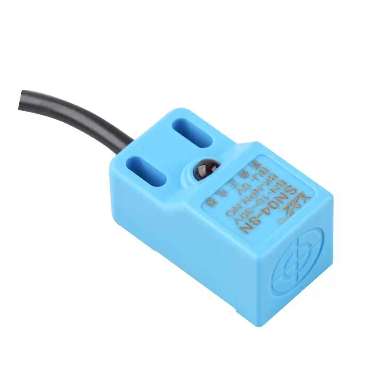
For close-range, non-contact detection of a metal machine part, an inductive proximity sensor is usually the first technology to evaluate. It detects conductive targets through electromagnetic induction, but the usable distance still depends on the exact metal, target size, sensor construction, mounting, temperature, and surrounding steel.
Start with an inductive proximity sensor and validate the exact target material.
Use a purpose-built industrial metal detector with a validated reject process.
Consider photoelectric or ultrasonic sensing when material identity is not required.
Use a Hall, reed, or magnetic sensor designed for the field and mounting geometry.
The direct answer
An inductive proximity sensor detects a nearby metal target without touching it.
The sensor creates an alternating magnetic field at its active face. When a conductive metal target enters that field, eddy-current losses change the coil impedance. The electronics detect that change and switch an output for a PLC, relay, counter, or machine controller.
This makes inductive sensing a practical choice for confirming a steel fixture, counting metal blanks, checking a gear position, detecting a bolt, verifying a closed metal guard, or establishing an end position on a machine axis.
Match the technology to the job
Four metal-detection questions that look similar but need different equipment
Start with what the machine must know. A fixed proximity switch, a long-range presence sensor, a magnet sensor, and a product-inspection detector solve different problems even when every problem mentions metal.
Is a metal part at this point?
Use an inductive proximity sensor when the target is close and metal identity matters.
Did any object cross the conveyor?
Use a photoelectric or ultrasonic sensor when metal selectivity is unnecessary.
Is metal hidden inside the product?
Use an industrial metal detector designed around the product, packaging, aperture, and reject system.
Did a magnet reach the switch point?
Use a Hall, reed, or magnetic sensor. It responds to a magnetic field, not arbitrary unmagnetized metal.
Detection principle
How does an inductive sensor detect metal?
The useful mental model is energy loss in an electromagnetic field. It explains why conductive targets switch the sensor, why non-metal barriers can sometimes be used, and why target material and geometry affect the installed distance.
The oscillator drives a coil
An alternating magnetic field forms in front of the sensor's active face.
Metal enters the field
The conductive target supports circulating eddy currents induced by that field.
The coil behavior changes
Eddy-current losses alter the coil impedance and reduce or shift the oscillator signal.
The output switches
The evaluation circuit changes the NPN, PNP, relay, or other model-specific output state.

Metal type matters
Can the same inductive sensor detect steel, stainless steel, aluminum, brass, and copper?
Often yes, but not necessarily at the same distance. A sensor's published nominal distance is tied to a defined reference target and test conditions. The response to another alloy depends on that sensor's coil design, frequency, signal processing, target dimensions, and mounting.
Do not apply one universal correction factor to every manufacturer's range. Use the reduction-factor or sensing-distance data for the exact part number, then test the real production target.
Interactive selection helper
What sensor should you use for your metal-detection task?
Select the job that best matches your application. The result identifies the technology to evaluate first and the evidence needed before purchase.
Choose the task
Start with
Inductive proximity sensor
Best first choice for short-range confirmation of a metal workpiece, gear, cam, fixture, bolt, or machine position without contact.
Mechanical installation
Flush and non-flush sensors create different fields and need different brackets.
The construction determines whether surrounding metal can sit beside the active face. Catalog terms vary, so use the mounting drawing and clearance dimensions for the exact part number.
Built for installation level with surrounding metal
- Useful where the sensor must be protected inside a metal bracket.
- The forward field is more contained than a comparable non-flush design.
- Facing-metal and adjacent-sensor clearances still come from the data sheet.
Needs a metal-free zone around the active head
- Often selected when additional range is needed in the same housing class.
- Side-field interaction makes bracket geometry more critical.
- Never substitute a guessed "one diameter" or "three diameters" rule for the model drawing.
Usable sensing margin
Rated distance is not the same as your guaranteed installed gap.
The catalog value is established under defined test conditions. Your working point should remain inside the model's specified set-distance or assured operating zone after target, temperature, voltage, tolerance, runout, vibration, and contamination are considered.
A smaller target can couple less strongly with the field. An off-center or angled target can cross a different portion of the field. Nearby steel can shift the response. Temperature can move the switch point. These effects are why a robust installation is designed around margin, not around the maximum number printed in a table.
Target material
Steel, stainless alloys, aluminum, brass, and copper can produce different responses.
Target size and thickness
The published value uses a defined reference target that may be larger than your part.
Approach and alignment
Lateral movement, tilt, runout, and repeatability change where the target crosses the field.
Machine environment
Heat, vibration, surrounding metal, mutual interference, oil, coolant, and cable noise all matter.
Technology comparison
When is another sensor better than an inductive proximity sensor?
Inductive sensing is the default for local metal presence, not a universal answer for every application containing metal. Use this comparison to prevent a category error before discussing model numbers.
| Technology | What it responds to | Best-fit task | Main limitation to verify |
|---|---|---|---|
| Inductive proximity | Conductive metal in a localized electromagnetic field | Close-range machine position, part presence, counting, and end stops | Material, target size, mounting metal, set distance, and output compatibility |
| Capacitive proximity | Change in capacitance from metal or non-metal targets | Level or presence of resin, liquid, powder, glass, wood, or metal | Not metal-selective; moisture, buildup, and surrounding material can affect setup |
| Photoelectric | Light interruption or reflection | Longer-range object presence, counting, and position where material identity is unimportant | Optical alignment, contamination, surface reflectivity, shape, and background |
| Ultrasonic | Returned sound energy | Distance or presence of many material types where optical contrast is difficult | Target angle, acoustic dead zone, air movement, temperature, and nearby echoes |
| Magnetic / Hall / reed | A magnetic field or magnet | Magnet-tagged pistons, door position, and sealed mechanisms | An ordinary unmagnetized metal part is not automatically a valid target |
| Industrial metal detector | Disturbance caused by metal passing through a detector field | Foreign-metal inspection in a product stream, package, powder, or bulk material | Product effect, packaging, aperture, contaminant type, test pieces, and reject validation |

Controls integration
The correct detection principle can still fail with the wrong output or wiring.
After choosing the sensor family, match the electrical interface to the machine. Confirm the supply-voltage range, NPN or PNP transistor output, normally open or normally closed logic, 2-wire or 3-wire connection, maximum load current, residual voltage, leakage current, connector pinout, and cable length.
Response time must be checked against target speed and the controller's input filter or scan behavior. Do not assume every inductive sensor uses 10 to 30 V DC or that every model switches in under 2 ms; AC, AC/DC, DC 2-wire, DC 3-wire, analog, and communication-enabled designs also exist.
Before requesting a model
Send these six facts to get a useful metal-sensor recommendation.
A complete application description prevents the supplier from selecting against a nominal gap while missing the real target, bracket, environment, or controller.
Exact metal and smallest target
Give the alloy or part sample, dimensions, thickness, surface condition, and whether several metals run on one line.
Minimum and maximum gap
Include runout, tolerance, vibration, approach direction, speed, and the point where the output must change.
Mounting metal and available space
Share a drawing or photo showing facing metal, side metal, adjacent sensors, thread size, and connector clearance.
Temperature and exposure
List ambient and target temperature, coolant, oil, chips, washdown, chemicals, dust, pressure, vibration, and shock.
Power and controller input
State voltage, NPN or PNP, NO or NC, wire count, connector, cable length, load, and required response time.
Acceptance test
Define successful detection, allowable false trips, sample size, hot/cold limits, line speed, and maintenance access.
Commissioning and troubleshooting
Diagnose the application before replacing the sensor.
A bench test can pass while the installed machine misses parts. Use the symptom, likely cause, and corrective check together.
Application review
Need a metal sensor that still works after it is installed?
Send XSZ the target and bracket details before you lock the machine drawing. We can compare sensing principle, housing size, mounting style, working margin, environmental construction, and output interface against the real application.
- Target alloy and minimum dimensions
- Minimum, normal, and maximum gap
- Bracket drawing and approach direction
- Temperature, oil, coolant, washdown, or chips
- Supply voltage and PLC input type
- Required connector, cable, and response behavior
Continue the selection
Related XSZ sensor guides
Use these pages for the next decision: model family, working-distance trade-offs, and PLC output logic.
Frequently asked questions
Questions about sensors that detect metal
Does a proximity sensor detect aluminum?
Many inductive proximity sensors can detect aluminum because it is conductive, but the switching distance may differ from the published steel-reference distance. Check the exact model's material data and test the real aluminum target. Consider an all-metal or reduction-factor-1 model when mixed-metal consistency is important.
Can an inductive sensor detect metal through plastic?
It can be possible when the barrier is nonconductive and the metal target remains inside the model's validated sensing zone. Add the plastic thickness, air gap, tolerance, and target movement to the total geometry. Verify the plastic does not contain conductive filler or metal reinforcement.
Can an inductive sensor detect stainless steel?
Many models can, but stainless grades do not all produce the same response. Provide the exact alloy or a sample and confirm the model-specific sensing distance under the real mounting conditions.
How far can an inductive proximity sensor detect metal?
There is no single maximum that applies to the entire technology. Available distance depends on sensor size and design, whether it is flush or non-flush, the target material and dimensions, and the installation. Select from the exact catalog data rather than a universal 50 mm, 60 mm, or 80 mm rule.
Will a Hall-effect sensor detect any steel part?
Not automatically. Hall and reed sensors are selected to detect a magnetic field, often from an installed magnet or magnetized component. An ordinary unmagnetized steel target may not create the required field at the switch location.
What is the difference between a metal detector and an inductive proximity sensor?
An inductive proximity sensor watches a small fixed zone near a machine and reports the presence or position of a metal target. An industrial metal detector inspects a product stream or package for hidden metal contamination and must be selected and validated with the product, packaging, aperture, contaminant samples, and reject process.
Why does the sensor work on the bench but miss parts on the machine?
The production target may be smaller, made from another alloy, moving laterally, tilted, hotter, farther away, or surrounded by more metal than the bench target. Bracket vibration, mutual interference, output wiring, PLC filtering, and pulse duration can also create an installed failure.
Technical basis and media
References and image credits
Technical references
- Official proximity sensor technical guide: inductive, capacitive, and magnetic detection principles; selection factors; mounting and environment considerations.
- Official photoelectric sensor technical guide: through-beam, retro-reflective, diffuse, and distance-settable optical detection.
- IEC 60529: enclosure protection classification. An IP code must be matched with the complete chemical, temperature, pressure, and washdown application.
- Industrial product-inspection technology guide: metal detection in product streams and the effect of metal contaminants on the detector field.
Image credits
- Hero factory image: Pexels, free-to-use photo.
- Metal gears image: Tim Mossholder on Pexels.
- Factory control image: Bulat843 on Pexels.
- XSZ proximity sensor image: XSZ Sensor product media.
Engineering note: this guide explains selection logic, not a substitute for the exact model data sheet, installation drawing, applicable machine risk assessment, or validation test. Specifications and clearances must be confirmed for the selected part number.