NO vs NC Sensor Output: Choose the Right Signal Logic.
Learn the difference between normally open and normally closed sensor outputs, how target presence changes the signal, and what to check before ordering proximity, photoelectric, fiber optic or magnetic sensors.
- Normally open vs normally closed explained
- Target-present and target-absent output states
- PLC program logic and machine safety considerations
- Replacement checklist for NO, NC and dual-output sensors
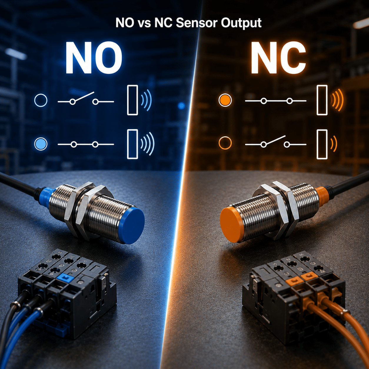
What is the difference between NO and NC sensor output?
NO and NC describe the default output state of a sensor and how the output changes when a target is detected.
NO sensor output
- NO means normally open.
- In many sensor applications, the output is OFF when no target is detected.
- The output turns ON when the target enters the sensing area.
- Often used when the machine only needs a signal during target presence.
NC sensor output
- NC means normally closed.
- In many sensor applications, the output is ON when no target is detected.
- The output turns OFF when the target enters the sensing area.
- Often used when the controller must monitor a normally active signal.
NO vs NC output state with and without a target
This simplified table helps buyers understand the output state before matching the sensor to PLC logic. Always confirm the exact datasheet for the selected model.
| Sensor logic | No target detected | Target detected | Typical meaning for controller |
|---|---|---|---|
| NO output | Output OFF | Output ON | Signal appears when the target is present |
| NC output | Output ON | Output OFF | Signal disappears when the target is present |
| NO + NC dual output | One output OFF, the other ON | States reverse when target is detected | Useful when the controller can choose either logic |
| Programmable output | Depends on amplifier or sensor setting | Depends on amplifier or sensor setting | Confirm saved parameter and operator access |
NO/NC is not the same as NPN/PNP
Buyers often mix these terms. You normally need to confirm both the electrical output type and the signal logic.
NO or NC
Describes whether the output is normally open or normally closed relative to target detection.
NPN or PNP
Describes whether the output transistor sinks or sources current for the PLC input.
Both must match
A sensor can have NPN NO, NPN NC, PNP NO, PNP NC or dual-output versions depending on the model.
When should you choose NO or NC output?
The right choice depends on the machine program, normal operating state and what should happen when the target appears or disappears.
Signal only needed on detection
Use NO when the PLC should receive an active signal only when a part, label, metal target or object is detected.
Normal state should be active
Use NC when the controller expects a normally active signal and needs to detect when that signal opens.
Logic may change later
Dual NO/NC output can help when replacement requirements vary or the controller program may use either logic.
Follow the machine standard
For repeated production, keep output logic consistent across stations to reduce wiring and maintenance mistakes.
Match the old sensor
If replacing a sensor, match the original NO/NC logic unless the controller program or wiring is being changed.
Check the PLC program
The program may expect a signal ON for target present, target absent, home position or interlock state.
The PLC program decides how the sensor signal is interpreted.
Changing from NO to NC can make the input look inverted. The sensor may work electrically, but the machine sequence may behave incorrectly if the program expects the opposite state.
- Confirm whether target present should mean PLC input ON or OFF.
- Check alarm, interlock, counting and home-position logic separately.
- Do not change NO to NC without reviewing program logic.
- For replacement orders, keep the original output logic when possible.
- When in doubt, test the sensor with the real controller input.
Counting signal
Many counters expect a pulse when the target passes, which often fits NO logic.
Presence confirmation
The PLC may expect input ON when the part is present or ON when the station is clear.
Alarm condition
Some machines monitor a normally active input and alarm when the signal turns OFF.
Can NC output be more suitable for monitoring and alarms?
In some control circuits, a normally active signal can make signal loss easier to detect. However, safety-related functions must be designed according to the machine safety system, not by sensor logic alone.
NC can help when
- The controller should monitor a normally active signal.
- The application needs to notice signal loss or open-circuit-like behavior.
- The PLC program is written for active-normal operation.
- The machine standard already uses NC for similar checks.
Do not assume
- NC output alone does not make a machine safety-rated.
- Safety light curtains and safety circuits need proper safety design.
- Risk assessment, response time and safety controller requirements still matter.
- Standard sensors should not replace certified safety devices.
NO/NC output is affected by wire count and model design
Some sensors provide only one output logic. Other models provide both NO and NC outputs or allow settings through an amplifier.
| Sensor type | Typical output logic | What to check | Buyer risk |
|---|---|---|---|
| 3-wire single output | NO or NC depending on model | Model suffix and wiring diagram | Similar sensor body may have opposite logic |
| 4-wire dual output | Often provides both NO and NC outputs | Which wire is NO and which wire is NC | Connecting the wrong output wire inverts the signal |
| 2-wire sensor | NO or NC by model | Leakage current, voltage drop and load compatibility | May not replace a 3-wire sensor directly |
| Amplifier-based sensor | May be programmable | Saved output mode and teach settings | Settings can be changed by operators or reset during replacement |
Which industrial sensors commonly use NO or NC output?
NO and NC output logic is common across many sensor families. The right logic must match the machine program and wiring standard.
Proximity sensors
Inductive and capacitive sensors may be ordered as NO, NC or NO+NC depending on series.
Photoelectric sensors
Optical sensors often support light-on, dark-on, NO, NC or selectable output logic by model.
Fiber optic amplifiers
The amplifier usually controls the output logic and may allow teach or mode settings.
Magnetic switches
Cylinder switches may have NO or NC versions for end-position feedback.
Color mark sensors
Packaging lines need correct signal logic for mark detection and registration timing.
Safety-related devices
Safety products use dedicated safety outputs and should be selected according to the safety system.
How to replace a sensor without changing the signal logic
Use this quick workflow before replacing an installed sensor. It prevents the common mistake of buying the same shape with the opposite output logic.
Read old model
Check the model suffix, label and wiring diagram for NO, NC or dual output.
Check PLC state
Confirm whether target present should make the controller input ON or OFF.
Match full details
Confirm NO/NC, NPN/PNP, voltage, wire count, connector and sensing distance.
Common NO and NC sensor output mistakes
Most output-logic problems appear after installation because the sensor turns on but the machine responds in the opposite way.
Risky approach
- Choosing only by housing size, thread or sensing distance.
- Assuming NO and NC can be swapped without program changes.
- Mixing up NO/NC with NPN/PNP output type.
- Using a 4-wire sensor but connecting the wrong output wire.
- Replacing programmable amplifiers without checking saved output mode.
Better approach
- Confirm what the PLC should see when the target is present.
- Match NO/NC, NPN/PNP and wire count together.
- Use old model suffix, datasheet or wiring photo for replacement.
- Label dual-output wires clearly during installation.
- Test output state with real machine logic before production.
If the sensor works but the machine logic is wrong, check NO/NC first
An inverted signal often looks like a PLC problem, but the cause may simply be the wrong output logic or wrong output wire.
Signal is inverted
Likely cause: NO sensor was replaced with NC, or NC was replaced with NO.
First check: Compare target-present input state with the old sensor.
Machine starts at wrong time
Likely cause: PLC program expects the opposite normal state.
First check: Review sequence logic and input comments.
4-wire sensor behaves wrong
Likely cause: The NO and NC output wires were swapped.
First check: Confirm wire color and pin assignment.
Works in manual test
Likely cause: Manual test checks LED only, not PLC logic.
First check: Watch the PLC input state during real target detection.
Alarm is always active
Likely cause: NC monitoring circuit now receives NO behavior.
First check: Confirm expected normal input state.
Replacement changes cycle
Likely cause: New model matches shape but not output logic.
First check: Compare complete model suffix and datasheet.
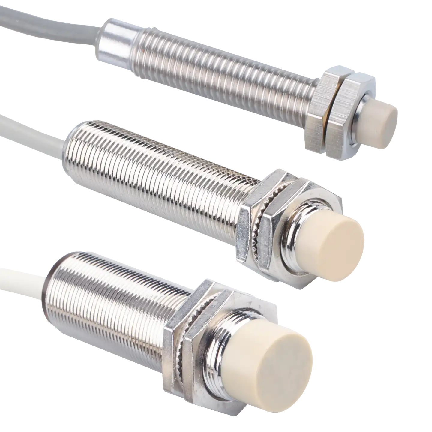
Send these details before choosing NO or NC output.
For replacement or OEM orders, XSZ can help match the output logic if you share how the controller should react when the target is present.
Continue with sensor wiring and selection resources
After confirming NO or NC output logic, continue checking electrical output type, sensor category and application details.