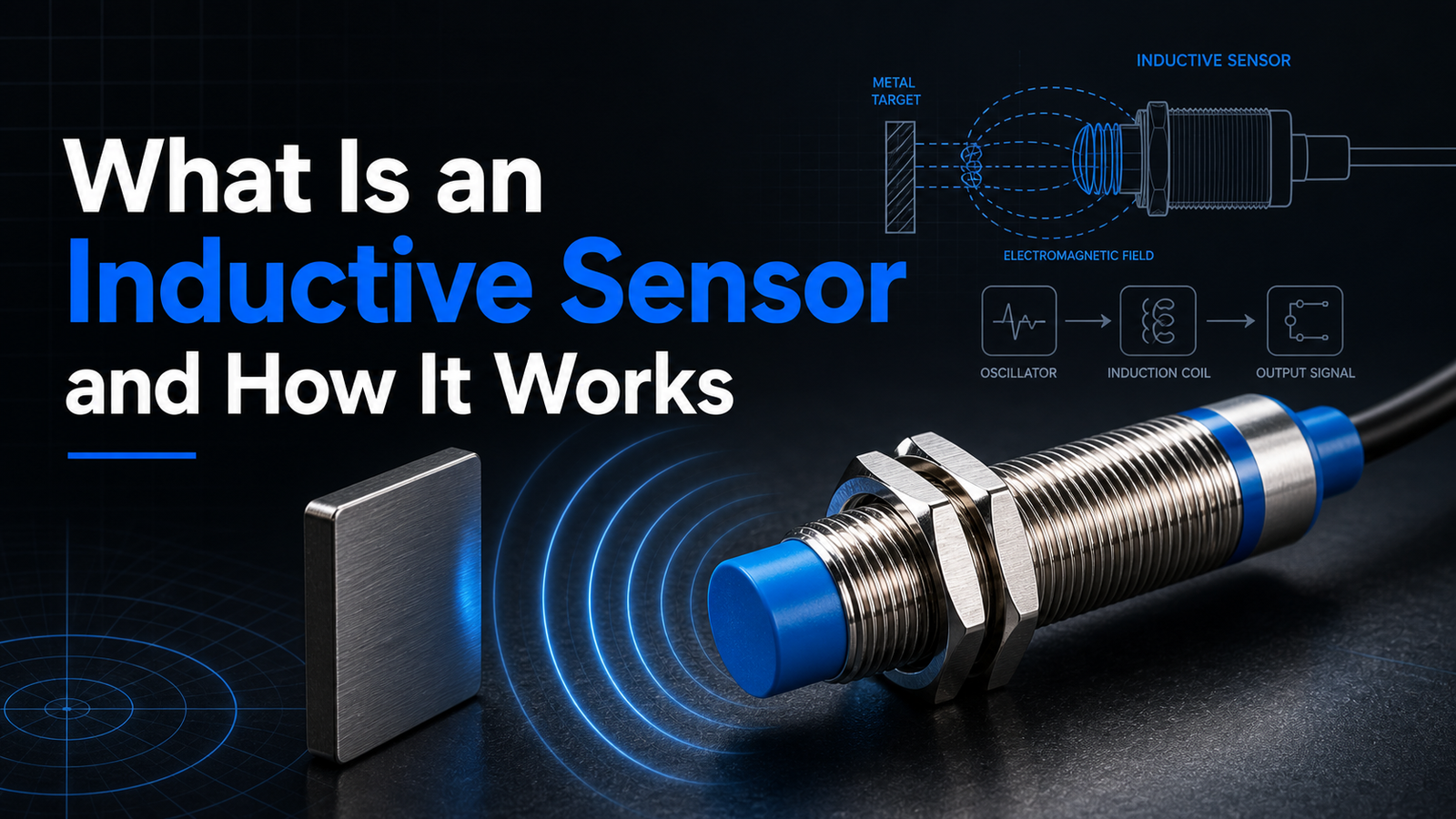
An inductive sensor is a non-contact electronic device that detects nearby metallic objects using electromagnetic induction and changes in inductance. When metal enters the sensor’s high-frequency field, eddy currents form and drain energy, triggering detection—without any physical contact. Typical sensing ranges run from 0.5 mm to 40 mm[1], with switching frequencies reaching up to 5,000 Hz on fast models. These sensors detect only metals like steel, aluminum, and brass, never plastic or wood, and ferrous metals achieve full range while aluminum reduces it by roughly 60%.
What parts actually make it up? How does it differ from a capacitive sensor? Which specifications matter when you go to choose one? And where do factories tend to use them?
Quick Takeaways
- Detect only metals—steel, aluminum, brass—never plastic, wood, or glass.
- Choose sensing ranges from 0.5 mm to 40 mm[2].
- Inside: oscillator, LC coil, trigger circuit, and output stage.
- Pick fast models with switching frequencies up to 5,000 Hz.
- Expect aluminum targets to cut sensing range by roughly 60%.
What Is an Inductive Sensor?
An inductive sensor is a non-contact electronic device that spots nearby metal objects using an electromagnetic field and changes in inductance, which basically means it senses shifts in the magnetic field it puts out. The sensing face throws out a high-frequency electromagnetic field. When a metal target moves into that field, tiny circulating currents, called eddy currents, form inside the metal and drain energy out of the field. The sensor picks up on that drop in energy and switches its output on or off.
Since nothing physically touches the target, there really is nothing to wear down from contact, and that is exactly why these sensors handle dependable metal detection in dirty, wet, or shaky industrial spaces where optical or mechanical switches tend to give out.
What are the core parts inside an inductive sensor?
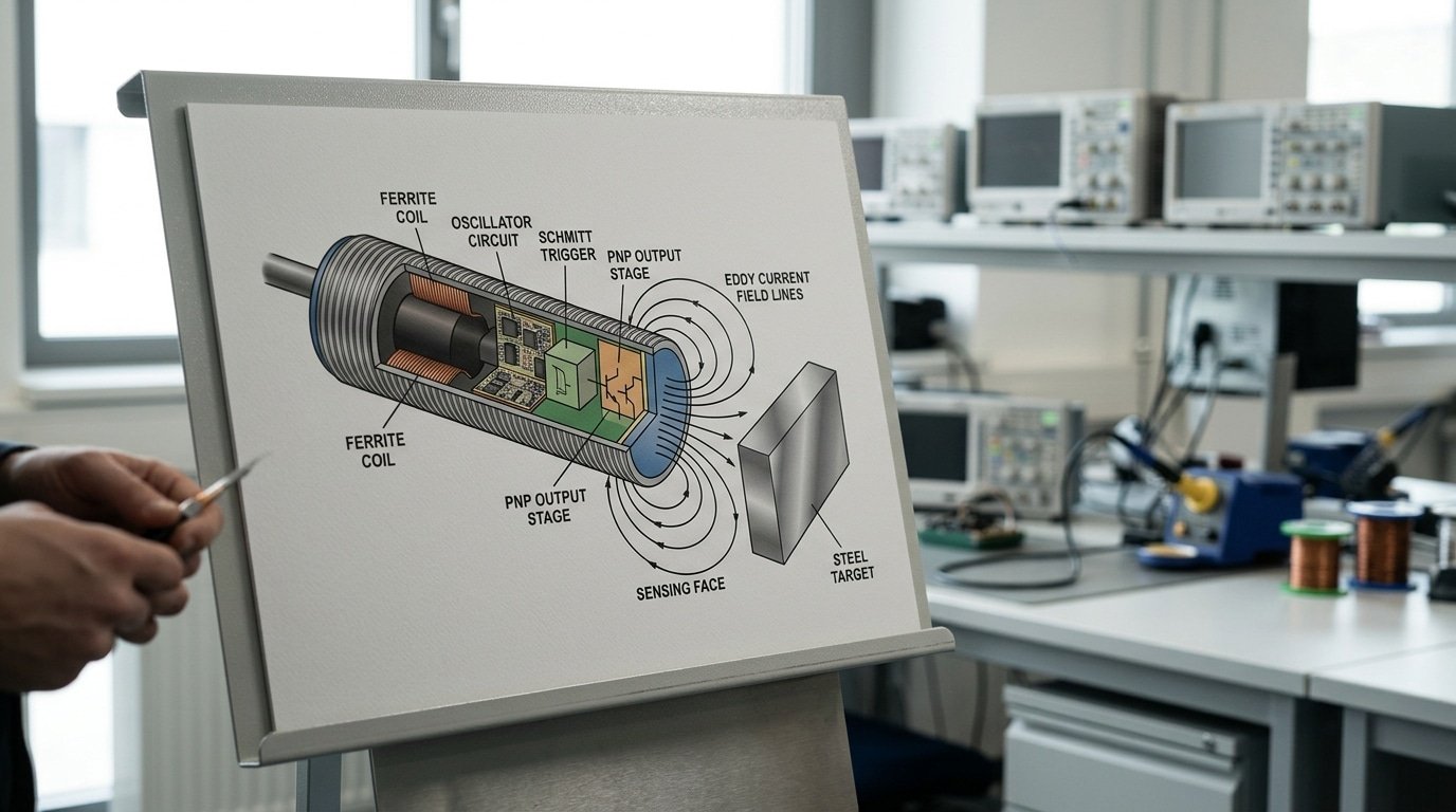
There are four components doing the actual work here, and each one has its own job to do:
- Coil (usually wound on a ferrite core): this generates the high-frequency field at the sensing face, and it typically runs anywhere from 100 kHz to 1 MHz.
- Oscillator: this drives the coil and keeps the field steady until metal comes along and pulls energy out of it.
- Trigger circuit (Schmitt trigger): this watches how strong the oscillation is and fires at a set point, adding a little hysteresis, meaning a buffer zone, so the output doesn’t rapidly flicker back and forth near that switch point.
- Output stage: this hands off a clean binary signal, either PNP or NPN, and either normally open or normally closed, to a PLC controller or a relay.
Here is a practical tip worth keeping in mind. Never mount a standard sensor flush into a metal bracket unless the label says it’s actually “flush-mountable.” Non-flush models need a metal-free zone around the head, otherwise the surrounding steel triggers false switching. Considering how often it happens, this one single mistake causes a large share of field faults when equipment is first getting started up.
How Does an Inductive Sensor Work?
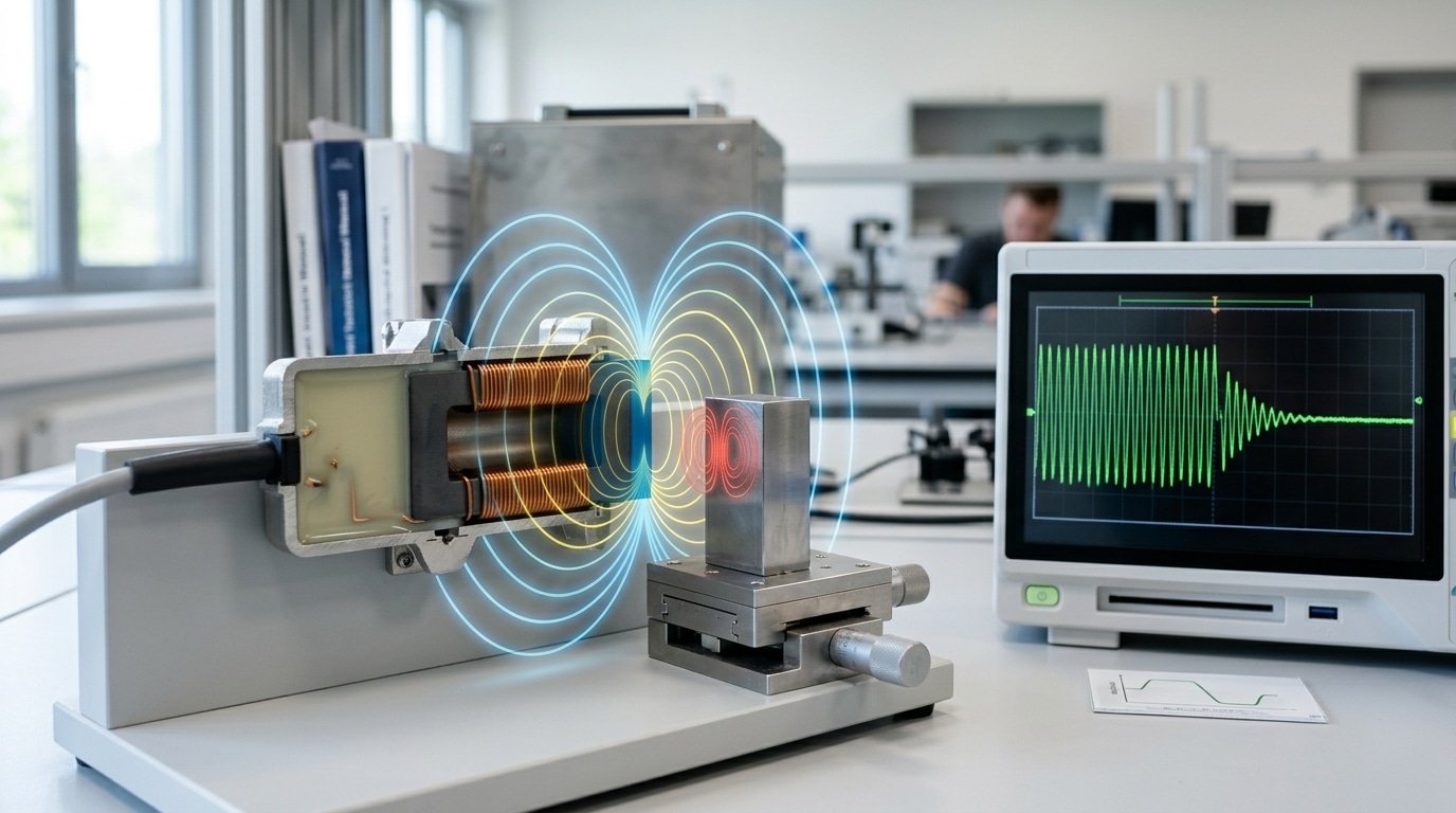
An inductive sensor works by running a high-frequency oscillating magnetic field from a coil, then watching that field weaken when metal enters it. When a metal target gets close, the sensor’s oscillation amplitude drops enough to flip the output. This lets it detect metal without any physical touch.
Here is the operating cycle, step by step:
- Coil generates the field: An oscillator drives a coil wound on a ferrite core, creating a high-frequency electromagnetic field that projects out from the sensor face.
- Metal target enters: A conductive object—steel, aluminum, brass—moves into that active field zone.
- Eddy currents form: The changing field induces tiny swirling electric currents on the metal’s surface. Think of them as small whirlpools of electricity.
- Amplitude drops: These eddy currents pull energy out of the field, so the oscillation gets weaker.
- Trigger switches output: A detection circuit sees the amplitude fall below a set threshold and switches the output signal on or off.
The eddy current effect is the heart of it. Faraday’s law says a shifting magnetic field creates currents in nearby metal (eddy currents). Those currents fight the original field, draining its strength, and how much strength they drain depends on the metal.
A practical tip: eddy current strength depends on the metal’s conductivity. Mild steel triggers the sensor at full rated distance, while aluminum or copper cuts the range by 30,approximately 60% because they react differently. Always check the “reduction factor” in the datasheet before mounting near non-ferrous parts.
Why Do Inductive Sensors Only Detect Metal?
Inductive sensors only detect metal because they rely on eddy currents, which form only in electrically conductive materials. No conductivity, no eddy currents, no signal. Plastic and wood have no free electrons to move, so they steal zero energy from the coil, the oscillator amplitude never drops, and the sensor never switches. That’s why industrial inductive proximity sensors stay blind to plastic, wood, water, and oil.
Why Does Sensing Distance Change by Metal Type?
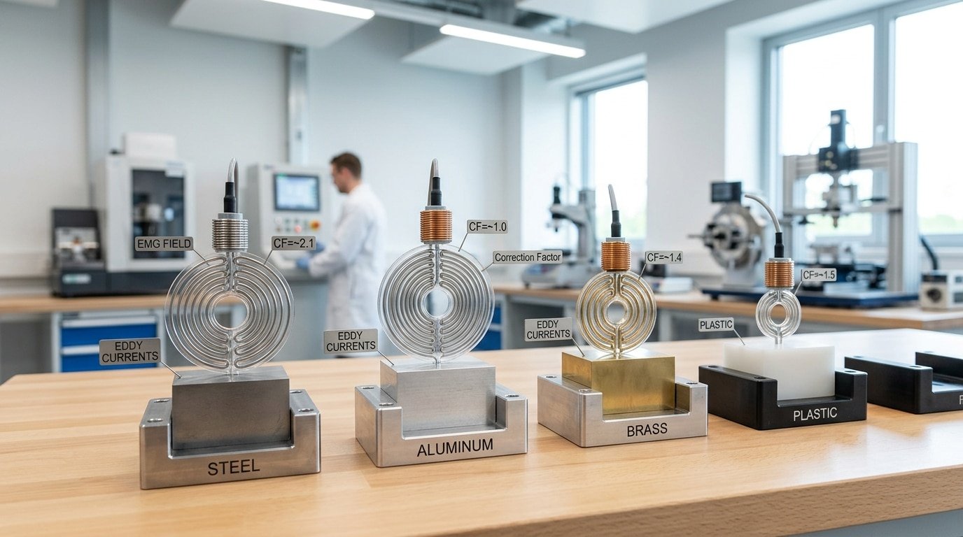
Sensing distance changes because different metals soak up field energy at different rates. Mild steel is magnetic and highly conductive, so it triggers at the full rated range. Aluminum, brass, and copper conduct well but are non-magnetic, so they weaken the response and cut the range. Engineers apply a correction factor to fix your effective distance.
| Target metal | Correction factor | Effect on range |
|---|---|---|
| Mild steel (Fe 360) | 1.00 | Full rated distance |
| Stainless steel | 0.70 | 30% shorter |
| Brass | 0.50 | Half range |
| Aluminum | 0.40 | 60%[4] shorter |
| Copper | 0.35 | 65% shorter |
Practical tip: always multiply the datasheet range by these factors before mounting. A sensor rated 8 mm for steel only reaches 3.2 mm for aluminum. Ignore this, and your machine misses the target every cycle.
What Is the Typical Sensing Range and What Limits It?
Inductive sensors generally pick up metal from roughly 1 mm out to about 40 mm[5] away, and that depends on how big the coil is and how the sensor is mounted. The operating distance (sensing range) is defined as the point where a standard steel target will reliably set off the sensor. So a small M8 barrel sensor might only reach about 2 mm, while a larger M30 unit can stretch out to 15 mm or even more than that.
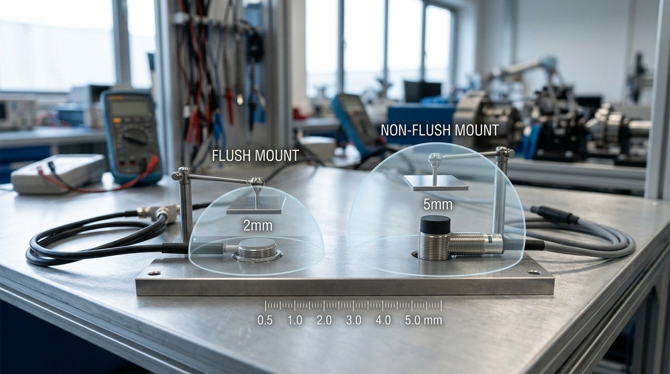
There are two mounting styles that set the starting point. Flush, or shielded, sensors sit level with the metal around them, and they offer a shorter range because that surrounding metal soaks up part of the field. Non-flush, or unshielded, sensors stick out past the metal and gain roughly 50 to approximately 100% more range, though they need a clear zone around the face so they don’t trigger falsely.
What Shrinks the Actual Detection Distance?
The size of the target and what it’s made of will cut the range quickly. The rated distance assumes a square plate of mild steel. If you swap in aluminum or brass instead, the range drops by a correction factor, and aluminum often reads near 0.35 of the nominal value. A target that’s smaller than the coil face will also shorten the distance quite a bit.
Why Doesn’t Nominal Range Equal Guaranteed Range?
The nominal range (Sn) is a lab figure, so it doesn’t match what you can actually count on out in the field. Manufacturers build in tolerances for temperature, swings in voltage, and the small differences from one unit to the next. The Guaranteed operating distance (Sa) usually comes out to only 81%[6] of Sn or even less than that. There’s also hysteresis, which is the gap between the switch-on and switch-off points, and that gap often runs 3 to approximately 15% of the range. It prevents chatter, but it does eat into the distance you can actually use. Generally, you’ll want to mount your target well inside Sa rather than right at the rated edge.
Choose an inductive sensor when your target is metal and sits within 40 mm; pick a different technology only when the target is non-metal or farther away. The choice hinges on target material, and inductive wins in dirty or wet conditions because dirt, oil, and moisture are non-metallic and stay invisible to the field (Eaton, 2025). Each technology has a job it does well and a job it fails at.
⚠️ Common mistake: Spec’ing a sensor’s rated range for an aluminum target, then finding it triggers too late or not at all. This happens because the rated distance assumes mild steel; aluminum, brass, and copper cut range by roughly 60%[7] due to weaker eddy-current losses. The fix: apply the material correction factor—size a 15 mm sensor when you need ~6 mm on aluminum.
| Sensor | Detects | Typical range | Relative cost | Best use case |
|---|---|---|---|---|
| Inductive | Metal only | 1–40 mm | Low | Position, counting on metal parts |
| Capacitive | Metal, plastic, liquid, wood | 1–60 mm[8] | Medium | Level sensing through tank walls |
| Photoelectric | Any opaque object | Up to several meters | Medium–high | Long-range object detection |
| Magnetic | Magnets, ferrous metal | Up to 70 mm | Low–medium | Cylinder piston sensing |
If-then guide:
- If the target is metal and close: pick inductive. It shrugs off coolant spray and swarf.
- If you must sense plastic, glass, or liquid level: pick capacitive.
- If range exceeds 40 mm or the object is non-metal: pick photoelectric.
- If you need to detect a piston inside a sealed cylinder: pick magnetic; the field passes through aluminum walls.
One pro tip: capacitive sensors trigger on water film and dust, causing false trips. That’s exactly where inductive sensors win.
Where Are Inductive Sensors Used in Industry?
Inductive sensors are used across industrial automation for position sensing, part counting, indexing, and end-of-stroke detection on metal components, according to Balluff automation data (2025). Their non-contact design means no wear from repeated triggering, so a single unit can run millions of cycles. That reliability is why they dominate factory floors.
Position feedback on machine tools. On CNC mills and lathes, inductive sensors confirm that a clamp, spindle, or slide reached its target position. They mount flush in metal fixtures and survive coolant spray. A photoelectric sensor would fog up; an inductive one ignores the mist entirely.
Part presence on conveyors. Metal blanks, cans, and bolts pass a sensor face at high speed. The sensor gives a fast binary “yes/no” so the PLC knows a part arrived. Switching frequencies of 1,5 kHz let it count small parts moving quickly without missing one.
RPM counting on gears. Point the sensor at a rotating steel gear. Each tooth passing the face produces one pulse. Divide pulses by teeth count to get shaft speed. Because the gear is already metal, you skip adding a target flag.
End-of-stroke on pneumatic cylinders. A small inductive sensor detects the metal piston or a machined groove, confirming full extension. Since dirt and oil in these environments are non-metallic, detection stays reliable in wet or harsh conditions (Eaton, 2025). This is what makes understanding what’s an inductive sensor so useful for machine builders.
What Are the Common Failure Modes and How Do You Troubleshoot Them?
The four most common inductive sensor failures are false triggers from nearby metal, temperature drift shrinking the sensing range, EMI noise from motors and VFDs (variable frequency drives), and cable damage from flexing. Most stem from mounting mistakes, not bad parts. Fix the install and reliability jumps.
Why Does My Sensor Trigger When Nothing Is There?
False triggers usually come from metal that sits too close to the sensor body or face. Mount two sensors side by side without spacing and their fields interfere,a problem called mutual interference. The rule: keep flush sensors at least two diameters apart, and non-flush units at least three. Also leave a metal-free zone around a non-embeddable sensor, or the surrounding steel frame gets detected instead of your target.
How Do Heat and Motors Wreck Readings?
Coil inductance shifts with temperature. Many sensors drift up to ±10%[9] of rated range across their full temperature spec, so a 10 mm sensor near a hot motor may only reliably switch at 6,7 mm. Derate: pick a sensor rated well above your gap. For EMI, motors and VFDs pump electrical noise into unshielded cables. Use shielded cable, ground the shield at one end only, and route sensor wires away from power lines. The electromagnetic interference basics explain why single-point grounding beats double.
Cable damage is the sneakiest fault. Repeated bending near a moving axis cracks conductors inside the jacket, causing intermittent dropouts. Use robotic-grade flex cable rated for millions of cycles, and secure a strain relief loop at the connector. Understanding what an inductive sensor needs to stay stable saves hours of chasing “random” faults.
How Do You Select and Mount an Inductive Sensor Correctly?
Selecting an inductive sensor comes down to five specs: mounting style, target material, switching frequency, output type, and IP rating. Get the target material wrong and you lose range fast, steel triggers at full distance, but aluminum and copper cut it by up to 65% unless you apply a correction factor. Since a sensor’s operating distance is rated for standard mild steel, always derate for other metals.
Flush or Non-Flush Mounting — Which Do You Need?
Choose flush (shielded) when you must embed the sensor in a metal fixture; choose non-flush (unshielded) when you need longer range and can leave the head exposed. Flush sensors sit level with surrounding metal without false-tripping. Non-flush types detect roughly 50%[10] farther but need a metal-free zone around the face.
What Are the Key Selection Specs?
| Spec | Options | Pick when |
|---|---|---|
| Output | PNP / NPN | PNP for most European PLCs, NPN for legacy Asian systems |
| Switch state | NO / NC | NC for fail-safe stops (wire break = signal loss) |
| Frequency | 10 Hz–5 kHz | High for fast-passing gear teeth |
| IP rating | IP67 / IP69K | IP69K for washdown or coolant zones |
How Far Apart Should Adjacent Sensors Sit?
Space two facing sensors at least 6× the sensing distance apart; space side-by-side flush sensors at least 2× the diameter. Too close, and their magnetic fields interfere, causing phantom switching. This spacing rule prevents the mutual coupling that ruins reliability in dense fixtures.
Frequently Asked Questions About Inductive Sensors
Quick answers to the questions engineers ask most about inductive proximity sensors, from barrier detection to wiring types and lifespan.
Can an inductive sensor detect metal through a non-metal barrier?
Yes. An inductive sensor detects metal through thin non-metal barriers like plastic, glass, or a conveyor belt, as long as the metal target sits within the operating distance. Industry data (2025) confirms these sensors ignore plastics, wood, water, and oil in the field. So you can mount one behind a plastic guard and still count metal parts on the other side.
What’s the difference between 2-wire and 3-wire types?
A 2-wire sensor connects in series with the load and needs no separate power line, but it leaks a small residual current (often 0.5,2 mA) even when off. A 3-wire type uses dedicated positive, negative, and signal wires, giving cleaner switching and near-zero leakage. Pick 3-wire (PNP or NPN) for PLC inputs; use 2-wire only for simple relay loads.
How long do inductive sensors last, and do they need calibration?
Because inductive sensors are non-contact and have no moving parts, they routinely run for 10 years or more with no wear. They need no periodic calibration, the oscillator amplitude threshold is set at the factory. Just check mounting torque and cable strain during scheduled maintenance.
Is an Inductive Sensor the Right Choice for Your Application?
Pick an inductive sensor when your target is metal and the environment is rough. These non-contact devices reliably operate in wet, dirty, or oily settings because dirt and moisture are non-metallic and stay invisible to the field. If the target is plastic, glass, liquid, or wood, an inductive sensor won’t see it, you need a different technology.
Match the sensor to the job with three quick checks:
- Target is metal, environment is harsh: Stay with an inductive sensor. Coolant, chips, and grease won’t cause false trips.
- Target is non-metal (plastic, paper, liquid level): Switch to a capacitive sensor, which reacts to any material’s dielectric change.
- Target is any object over a longer range (up to several meters): Use a photoelectric sensor instead, since inductive range tops out near 40 mm.
The honest limit is material: the answer to “what’s an inductive sensor best for” is dependable, contact-free metal detection where optical or capacitive types would foul or fail. Push it onto glass or fabric and it goes blind.
Your next step: write a short spec sheet before you buy. List target metal type, required sensing distance, mounting style (flush or non-flush), supply voltage, and output type (PNP/NPN, NO/NC). Send that sheet to a supplier and cross-check the datasheet’s rated operating distance against your real gap. Skip guessing. A five-line spec prevents the most common sourcing mistake, ordering a sensor whose range or output logic doesn’t match your controller.
Reference Sources
- [1]en.wikipedia.org — supports: An inductive sensor is an electronic, non-contact sensor that detects nearby **metallic …
- [2]baumer.com — supports: An inductive sensor is an electronic, non-contact sensor that detects nearby **metallic …
- [3]sensorpartners.com — supports: An inductive sensor is an electronic, non-contact sensor that detects nearby **metallic …
- [4]datasensing.com — supports: Industrial inductive proximity sensors typically detect only **metal targets** and are l…
- [5]balluff.com — supports: Industrial inductive proximity sensors typically detect only **metal targets** and are l…
- [6]eaton.com — supports: Industrial inductive proximity sensors typically detect only **metal targets** and are l…
- [7]pepperl-fuchs.com — supports: The core of a typical inductive sensor is a **coil (often on a ferrite core)** driven by…
- [8]ifm.com — supports: The core of a typical inductive sensor is a **coil (often on a ferrite core)** driven by…
- [9]realpars.com — supports: Inductive sensors work by generating eddy currents in nearby conductive metal objects, w…
- [10]festo.com — supports: Standard inductive proximity sensors provide a **binary output signal** indicating wheth…




